Preface
OpenClovis Integrated Development Environment (IDE) User Guide provides information about the usage of OpenClovis IDE, a graphical development environment from OpenClovis Inc. that complements the OpenClovis platform. This guide helps you to configure, compile, and execute OpenClovis IDE to build the application. OpenClovis IDE is designed to simplify and accelerate the development of Telecom application software over OpenClovis platform. It provides a simple and powerful mechanism with easy drag-and-drop features, to create Resources and Components, and define the attributes and relationships between them. OpenClovis IDE graphical interface enables you to capture the Information Models through UML notations and save them as XML files.
Audience
OpenClovis IDE Guide is designed for system integrator's, designers, and system architects. To use the product, you must be aware of the fundamentals of design, development, operation, management and configuration of telecommunication and networking systems. You must also be familiar with C programming, UML notations, and have the basic knowledge of Linux.
Documentation Conventions
This guide uses different fonts and symbols to differentiate between document elements and types of information. These conventions are summarized in the following table.
| Notation | Description |
|---|---|
|
This font denotes the C code provided in various examples. |
| Cross reference |
This font denotes a hyperlink. You can click on the hyperlink text to access the reference location, which can be either a section within the User Guide or a URL link.A cross reference refers to a section name and accesses the first page of that section. |
|
Bold Text |
Menu items and button names. |
|
Italic Text |
Variables for which you enter values. |
![]() This indicates the presence of notes or annotations, related to the context of the document.
This indicates the presence of notes or annotations, related to the context of the document.
![]() This indicates that certain precautionary measures must be taken before performing a particular task.
This indicates that certain precautionary measures must be taken before performing a particular task.
![]() This indicates that additional information is provided to you.
This indicates that additional information is provided to you.
Document Organization
This guide is organized into various chapters to provide information on speci?c areas. The following table introduces the chapter names and a brief overview of the content
| Chapter | Overview |
|---|---|
| Chapter 1, Introduction to OpenClovis IDE | This chapter helps you understand the conceptual information, advantages and key features of OpenClovis ASP and IDE. |
| Chapter 2, Getting Started | This chapter provides information to launch and access IDE, create a workspace and a project. |
| Chapter 3, Understanding the User Interface | This chapter provides information about the IDE work environment. |
| Chapter 4, Setting Resource Properties | This chapter provides information about the properties that you can specify for the chassis, node hardware, hardware, and software resources in the Resource Editor. |
| Chapter 5, Defining Alarm Profiles | This chapter provides information about defining alarms to map to the resources . |
| Chapter 6, Setting Component Properties | This chapter provides information about the parameters that you can specify for the various components in the Component Editor. |
| Chapter 7, Configuring ASP Components | This chapter provides information about configuring ASP components within IDE. |
| Chapter 8, Configuring AMF | This chapter provides information to create the instances of the entities defined in a Component Editor using AMF Configuration. |
| Chapter 9, Configuring and Allocating Memory Configuration Profiles |
This chapter provides information about configuring and allocating memory configuration profiles to the various ASP components and the SAF components.. |
| Chapter 10, Creating and Using Template Groups | This chapter provides information about creating and using the template groups to generate the source code. |
| Chapter 11, Defining IDL | This chapter provides information about creating the IDL XML file that is used by the IOC links to provide communication between two or more components. |
| Chapter 12, Generating Source Code | This chapter provides information about generating the source code after you have completed building the model. . |
| Chapter 13, Building the Project | This chapter provides information about configuring and building the project after you have completed generating the source code. |
| Chapter 14, Making Project Images | This chapter provides information about generating run-time images for a target system. |
| Chapter 15, XML Representation of the Model | This chapter describes the organization and content of the XML files which are part of the Open Clovis project that can be read by the IDE and also Command Line Tools. . |
| Chapter 16, Creating and Building openSAF Project in IDE | This chapter provides information about how to create and build the openSAF project. |
| Chapter 17, Creating and Using Model Templates | This chapter provides information to create, use, export, and import model templates. |
| Chapter 18, Application Import/Export | This chapter provides information about Application Import/Export feature provided by OpenClovis IDE. |
| Chapter 19, Limitations | This chapter provides information about the limitations of IDE. |
| Chapter 20, Glossary of Terms | This provides complete information about all the terms and definitions specific to Open Clovis IDE. |
Related Documents
For additional information about OpenClovis products, refer to the following guides:
- SAFplus Platform Release Notes provides information about the software and the hardware required to install OpenClovis Application Service Platform (SAFplus Platform) and Integrated Development Environment (IDE). It summarizes the additional features and enhancements of the product since the previous release. It also summarizes the issues and limitations of the product and provides workarounds wherever applicable.
- SAFplus Platform SA-Forum Compliance describes the level of compliance of OpenClovis SAFplus Platform and its Application Programming Interface (API) with the relevant Service Availability Forum Specifications.
- SAFplus Platform Installation Guide provides the system requirements, installation procedure for OpenClovis SAFplus Platform, IDE, and the Evaluation System.
- SAFplus Platform Sample Application Tutorial explains the steps to create and build a sample model using OpenClovis IDE and OpenClovis SAFplus Platform. It also provides troubleshooting information for this process. This provides the logical first step in understanding the SAFplus Platform offering.
- SAFplus Platform Evaluation System User Guide provides all the required information to configure and run the sample models packaged within the Evaluation System. This document also provides good understanding of OpenClovis SAFplus Platform's functionality. This is the natural follow on to the OpenClovis Sample Application Tutorial as it builds on the example created in that document.
- SAFplus Platform SDK User Guide provides information about SAFplus Availability/Scalability Platform architecture, various SAFplus Platform components, and their interactions. This guide helps you to configure the OpenClovis SAFplus Platform components, compile, and execute the SAFplus Platform code to build your custom application.
- SAFplus Platform IDE User Guide describes the usage of Integrated Development Environment (IDE), a graphical development environment that complements the SAFplus Platform. This guide helps you to understand how to use the various features of the IDE to build the application.
- SAFplus Platform Log Tool User Guide provides information about the usage of OpenClovis Log Tool. OpenClovis Log Tool is an interactive utility that allows you to view binary log files in a readable format and hence monitor system errors, warnings, and other log information. Log Tool allows you to format the
.logfiles and filter them to view the required entries. - SAFplus Platform API Reference Guide [1] is provided for each component. It describes the Application Programming Interface (API), Service Model, and Management Information Model of the various OpenClovis Application Service Platform (SAFplus Platform) services. It helps the developer to understand the capabilities of the SAFplus Platform services and the APIs provided by these services.
- SAFplus Platform Console Reference Guide provides details about managing applications built on SAFplus Platform using the SAFplus Platform runtime debug console commands. SAFplus Platform Console commands can be used to manage, monitor, and test your application.
OpenClovis Online Technical Support
OpenClovis customers and partners can register on our Web site and receive personalized services and information. If you need any support or assistance while working on OpenClovis products, you can access the following: URL: http://www.openclovis.com. Send your queries to: support@openclovis.com. Open source community support is available at: http://www.openclovis.org/forum.
Documentation Feedback
We are interested in hearing from our customers on the documentation provided with the product. Let us know your comments and suggestions on improving the documentation at OpenClovis Inc. Send your comments to: support@openclovis.com. Or even better, edit (or comment in) the page on our documentation wiki located at http://help.openclovis.com.
Chapter 1
Introduction to OpenClovis IDE
OpenClovis Integrated Development Environment (IDE) is designed to simplify and accelerate the development of application service platforms for the telecommunication market place. Coupled with the OpenClovis ASP,this intuitive software solution streamlines the process of specifying the information model, High Availability (HA) aspects and the communication infrastructure of a system. OpenClovis IDE stores all information describing a project in well defined XML files that can be modi?ed by the user. Modeling of system resources and relationships are speci?ed using a graphical UML editor. This chapter familiarizes you with the main concepts and features of OpenClovis IDE.
- Basic Concepts
- OpenClovis IDE Features
- OpenClovis Value Proposition
1.1 Basic Concepts
OpenClovis IDE is an Integrated Development Environment (IDE) designed to simplify and accelerate the development of Telecom application software over OpenClovis platform. It provides a simple and powerful mechanism with easy drag-and-drop features, to create Resources and Components and de?ne their attributes and relationships between them. OpenClovis IDE enables you to capture this model through UML notations and then save them as XML files.
Openclovis IDE is built using the Eclipse platform, hereby it inherits some functionality from it. It has a modeling framework and code generation facility for building tools and other applications based on a structured data model, from a model speci?cation described in XML
![]() This document refers only to the features of the OpenClovis IDE product and not those of the Eclipse platform.
This document refers only to the features of the OpenClovis IDE product and not those of the Eclipse platform.
OpenClovis IDE enables you to rapidly create a model of the Resources and generates customized code for OpenClovis. Apart from enabling to easily generate code, it also provides the capability to compile and deploy the code to the target system under development.
OpenClovis IDE allows you to model the following elements:
- Physical Resources
- Logical Entities
OpenClovis IDE provides two basic views of the system; physical (or resource) view and logical (or component) view. These two views are linked with each other.
- Physical (or resource) view: The physical (or resource) view allows the modeling of the physical containment aspects of the system, working with chassis, blades, daughter cards, network ports, other physical devices, and software entities running on such cards and devices. The physical containment hierarchy is used to define the Managed Object(MO)tree and to derive the MO path (addressing) information.
- Logical (or component) view: The logical (or component) view is a service availability view of the system, using concepts such as cluster, nodes, service units, service groups, service instances, component service instances, proxy components, non-proxy components, and proxied components.
1.1.1 Information Modeling Using IDE
The OpenClovis Information Model is a generic framework or an abstract representation of the entities in a managed environment. The OpenClovis IDE enables you to build an Information Model using UML notation.
An Information Model (IM) presents a uni?ed view of different components of a system and abstracts hardware and software running on a system, from an end user. IM provides a uni?ed view and association of all the physical and logical objects in the managed environment.
The advantages of Information Modeling are:
- Managed Objects: Allows the de?nition of MOs for a OpenClovis-based system covering chassis management, devices, alarms, faults, component states, and provisioned attributes of OpenClovis components and customer applications.
- Strong integration with system model: Information model is created as the user is working on the system model. For instance, when an alarm is defined for a physical or logical component, the related alarm MO attributes are automatically added to the information model. *
- SNMP MIB import: To speed up MO definition and/or to design an information model that is compliant with existing models,one or more SNMP MIB files can be imported in to a OpenClovis IDEproject. The user can select one or more objects from the MIB tree and add them to an MO class definition. MIB attributes will become MO attributes with the same name, type, and access mode. To maintain compatibility with the MIB, SNMP OIDs are preserved and attribute names, type, and access modi?ers can be locked to prevent deviation from the imported model. SNMP traps can be added as alarms. If needed,proprietary attributes can be added to an imported object, resulting in a new object class.
- SNMP MIB export: Parts of or the entire newly defined information model can be exported as new, proprietary MIB(s).
- OID/MOIDmapping: OpenClovisIDE generates the necessary bi-directional mapping between the OIDs used by the SNMP agent and the MOIDs used by OpenClovis COR OpenClovis IDE.
For information about building a sample model using OpenClovisIDE,see OpenClovis Sample Application Tutorial .
1.2 OpenClovis IDE Features
OpenClovis IDE provides the following important features:
- Modeling: Modeling is performed using the Resource Editor and Component Editor pane, along with the definition of the relationship, and its validation. The properties of each of these resources are also set during the development of the Information Model.
- Configuration: Configuration is related to the configuration of modeled entities, OpenClovis components, alarms set for the resources, generated source code,and the generation of the configuration files needed for OpenClovis ASP customization, including build-time, boot-time, and run-time configuration ?les.
- Boot and run-timeconfiguration: OpenClovis IDE generates the various XML files used by OpenClovis. Boot-time configuration includes boot-levels, services to start per boot level, and node role profiles (personalities).
- Code generation for OpenClovis customization: To facilitate build-time customization for OpenClovis, OpenClovis IDE generates C header files to be linked with OpenClovis libraries to result in customized OpenClovis server executables. During code generation,the correct files are generated in the predefined directories and file structures.
- Application stub generation: OpenClovis IDE also generates application skeletons (stub code) for EOnized customer applications.
- Eclipse based IDE for System and Information Modeling: Powerful,Eclipse based graphical user interface for system modeling, information modeling, and ASP-based product development.
- UML Based: Model components and their relationship such as containment, aggregation, and inheritance, are edited using a graphical UML editor.
- Projects Based: Modeling work files are organized into projects. Many model artifacts are reusable across projects.
- XMI import: UML models (if satisfying certain restrictions) can be imported from other tools using XML Metadata Interchange (XMI) compliant files.
- Integrate with other IDE Tools : Due to its Eclipse based nature, IDE can be integrated with other Eclipse based IDEs.
- Template support: A library of pre-defined model fragments (templates) are provided, jump-starting the system modeling work when working with common objects such as standard chassis, system controller cards, line cards. For specific hardware models (chassis and cards) a palette of fully detailed and complete object models are available.
The following are a few additional features provided by the OpenClovis IDE:
- Facilitates easy drag and drop of resources and components.
- Validation of a model. View the existing projects in the OpenClovis IDE Workspace.
- Importing OpenClovis IDE Projects.
- View a MIB File through the OpenClovis MIB explorer.
- Generation of source code and configuration files.
- Outline view for editors.
1.3 OpenClovis IDE Value Proposition
OpenClovis solution offers the following benefits to its customers.
- Enhances developer productivity.
- Reduces time-to-market.
- Ensures re-usability of core development efforts.
- Offers platform-independent modeling and implementation.
- Increases development process consistency.
- Facilitates Platform component integration.
- Minimizes software footprint for optimized performance.
- Supports a broad range of industry standards such as,
- Advanced Telecom Computing Architecture (ATCA), Carrier Grade Linux (CGL), and SA Forum Application Interface Specification (AIS).
CHAPTER 2
Getting Started
This chapter provides information to launch and access IDE, create a workspace, and a new project.
Key Topics:
- Creating Project Area
- Launching OpenClovis IDE and setting Up My Workspace
- Creatin OpenClovis IDE Project
- Setting Project Properties
2.1 Creating Project Area
After installation, create a new project area at /home/clovis/projectarea1 by executing the command:
- <install_dir>/6.1/sdk/bin/cl-create-project-area /home/clovis/projectarea1
This will prepare /home/clovis/projectarea1 for use with the OpenClovis IDE and SDK.
A project area allows you to create and develop one or more system models with the required ASP-based components. The project area can hold multiple models and you can switch between these models. All the models in the same project area share the same ASP source tree,there by any modifications to the ASP source tree, are re-used across all the projects that are available in the project area.
After creating a new project area, you can create one or more system models with the required ASP based components.
2.2 Launching OpenClovis IDE and Setting Up My Workspace
You launch the OpenClovis IDE from the command line. If you chose to create symbolic links during installation you can simply enter cl-ide from any directory. If you did not create symbolic links during installation you can either:
- Add the installation directory to the shells search path and then launch the IDE. For example with a bash shell,
   # export PATH=$PATH:$install_dir/6.1/sdk//bin
   # cl-ide
or
* Execute the command
    # <install_dir>/6.1/sdk/bin/cl-ide
The splash screen for SAFplus Platform IDE is displayed
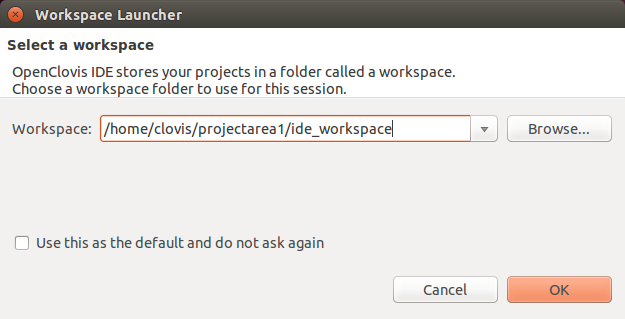
The Workspace Launcher window is displayed
Enter the location of the workspace and click OK. The value in this field will de- fault to the ide_workspace directory below the last project area that was created
using the cl-create-project-area command. If you wish to use a differ- ent workspace then select the ide_workspace directory under any other valid project area.
![]() To set the selected workspace as the default, select the Use this as the default and do not ask again checkbox.
To set the selected workspace as the default, select the Use this as the default and do not ask again checkbox.
If the error Workspace already in use is displayed when launching the OpenClovisIDE check the processes that are running. If the Eclipse process is running, then terminate the Eclipse process and re-launch OpenClovis IDE.
2.2.1 Understanding My Workspace
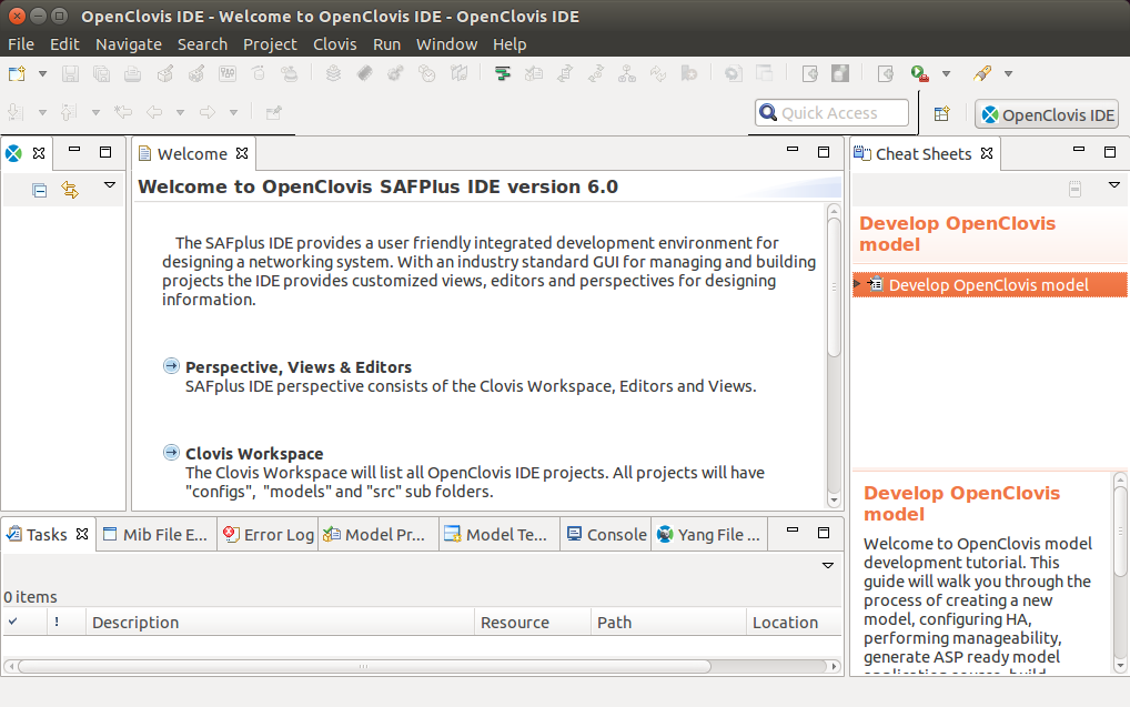
The Clovis Workspace pane displayed on the left side of the OpenClovis IDE window lists the projects that belong to that workspace in an alphabetical order. It also displays the defaul tfolders and files that are generated for every project. The generated files include OpenClovis configuration files, UI model files, templates, and scripts.
![]() These files MUST NOT be modified as this may lead to unexpected result and the model may become invalid.
These files MUST NOT be modified as this may lead to unexpected result and the model may become invalid.
The Open Clovis configuration files are not visible in the general project view.
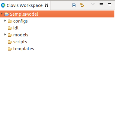
Initially, when you create a project, only the templates and idl folders are displayed in the Clovis Workspace pane. After the code generation step the src folder is also displayed. To display the other folders, click the arrow on the top right-corner of the Clovis Workspace pane and select Filters. The Navigator Filters dialog box is displayed. Clear the checkboxes for the folders that you need to view and click OK. If you clear all the checkboxes, then the folders shown in Figure OpenClovis IDE Workspace is displayed in the Clovis Workspace pane.
2.2.2 Viewing My Workspace
To view the workspace:
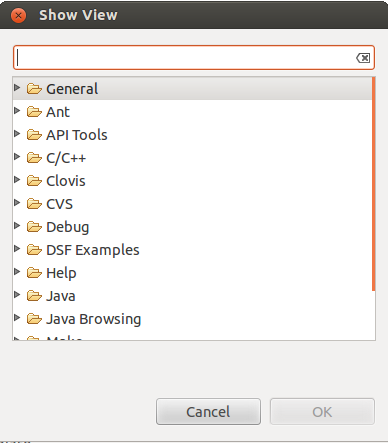
- From the Window menu, click Show View, and then click Other. The Show View dialog box is displayed.
- . Type the name in the text box or double-click Clovis and select Clovis Workspace.
- . Click OK. The Clovis Workspace pane is displayed.
2.3 Creating OpenClovis IDE Project
To you create a project, you can start with a blank project or specify the resources and components using the wizard. If you start with a blank project, you need to use the Resource Editor and Component Editor Palettes to create your resources and components. The Wizard helps you to kick start a project by creating standard sets of objects based on the entry of a few key pieces of information.
To create a new OpenClovis IDE project:
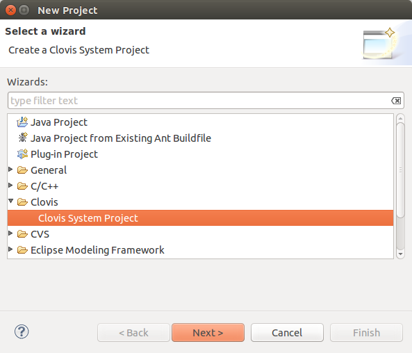
1. From the File menu, point to New, and then click Project.... The New Project Wizard is displayed.
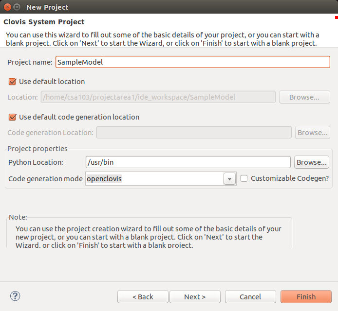
2. Type Clovis System Project in the text box or double-click Clovis, select Clovis System Project, and then click Next. The Clovis System Project window is displayed.
3. Enter the following information:
- Project name: Name for your project.
![]() Do not use spaces or special characters for the project name. The project name can be alphanumeric, but cannot start with a number.
Select Use default to retain the default location of the project, or enter the location of the project contents.
Do not use spaces or special characters for the project name. The project name can be alphanumeric, but cannot start with a number.
Select Use default to retain the default location of the project, or enter the location of the project contents.
- SDK Location: Enter the location where the OpenClovis SDK was installed. This field is automatically filled if IDE is installed as part of OpenClovis SDK installation. This is usually <installed_directory>/6.1/sdk.
- Project Area Location: Enter the location where the generated source code. and install images will be written. This field is automatically filled If IDE is installed as part of OpenClovis SDK installation.
![]() Usualy this location will be created before start the IDE by using cl-create-project-area script. If not cl-ide script should create this location.
Usualy this location will be created before start the IDE by using cl-create-project-area script. If not cl-ide script should create this location.
- Python Location: This is the path of the python binary location that will help OpenClovis IDE in generating the code. Python 2.4.1 is required to be installed in the required location before using OpenClovis IDE to generate code. Python is usually located in /usr/bin folder. If Python is installed as part of OpenClovis SDK installation, then it is located at <installation_directory>/buildtools/bin.
- Code generation mode: Select the code generation mode. Default value for this field is openclovis.
At any point from here on forward you can click Finish to create the project using the information that you have entered so far. If you choose to do this before getting to the end of the wizard you will need to create resources and components manually through the Resource and Component editors.
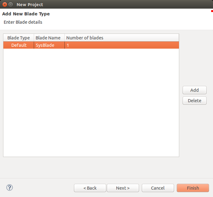
4. Click Next to specify the types and number of blades in your system. The Add New Blade Type window is displayed. Click Add to add a new blade type and enter it’s details.
- Blade Type: Type of the blade. Select the type of the blade from the dropdown list.
- Blade Name: Name for the blade type. This name must be unique within the model.
- NumberofBlades: Number of blades of this type that will be present. For information about blade types refer to the Glossary.
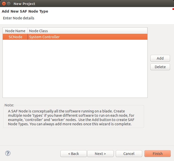
5. Click Next to specify the SAF node types in the system. The Add New SAF Node Type window is displayed. Click Add to add a new SAF node type and enter it’s details.
6. Enter the following information:
- Node Name: Name of the node type. This name must be unique within the model.
- Node Class: Type of class to which the new node type belongs. Select one of the following options from the drop-down list:
- System Controller : Select System Controller if this node type will act as a System Controller.
- Payload Select Payload if this node type will act as a worker node, typically running application code.
For information about node and node class refer to the Glossary
7. Click Next to specify the SAF service types for the system. The Specify Program Names window is displayed. Click Add to add a new program (SAF Service Type) and enter it’s details.
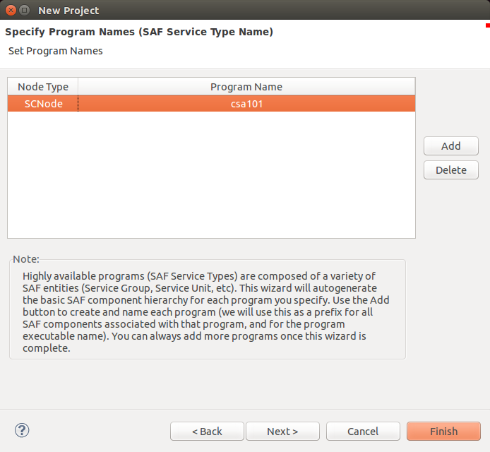
8. Enter the following information:
- Node Type: The type of node on which the program will run. Select from the list of node types defined on the previous page.
- Program Name: Name of the program being de?ned. All elements of the SAF Service Type (service unit, service group, etc.) will be derived from this name.
9. Click Finish. The Resource and Component Editors display the speci?ed blades and nodes along with their resources and components.
The Clovis Workspace pane lists the new project, its associated ?les, and directories. In this case,Sample Model is the name of the project. You can open and close projects in the Clovis Workspace by right-clicking and choosing Close/Open from the Clovis Workspace context menu.
2.4 Setting Project Properties
To set the properties for the project:
1. From the Project menu, choose Properties or right-click on the project and select Properties.
2. Select Clovis System Project. The Clovis System Project pane is displayed on the right-side.
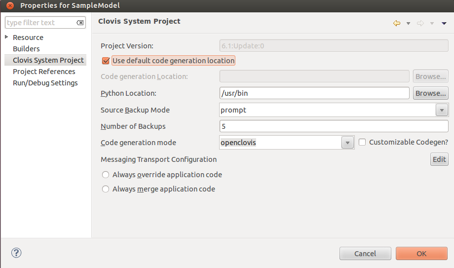 3. Enter the following information:
- Project Version: This is the version number of the project. This field is not editable.
- Code generation Location: Location where you want to generate the source for your model.
- Python Location: This is the path of the python binary location. Python is required by the OpenClovis IDE to generate code. Python is usually located in /usr/bin or in <sdk-dir>/build tools/bin if installed during ASP installation.
![]() If you have specified the SDK, Project Area, and Python location while creating a new project,they will appear in the SDK Location,Project Area Location, and Python Location fields in the Clovis System Project window. If not, you need to specify these locations in this window before you generate the code.
If you have specified the SDK, Project Area, and Python location while creating a new project,they will appear in the SDK Location,Project Area Location, and Python Location fields in the Clovis System Project window. If not, you need to specify these locations in this window before you generate the code.
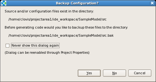
- Source Backup Mode: This option is used to indicate whether or not to backup the project’s existing source directory when new source code is generated. If the directory is not backedup then any manual changes that have been made to source ?les outside of the prescribed begin/end application code blocks or changes made to con?guration ?les will be overwritten. The possible values for this option are Always,Never,and Prompt. Prompt will ask the user each time that source code is generated.
- Number of Backups: This option indicates how many number of source code back up should be preserved. Number should between 1 and 100. Default is 5.
- Code generation mode: This option is used to select code generation option. IDE will generate the code with OpenClovis APIs If selected value is openclovis
![]() IDE will not support code merging if a user switches between SAF and OpenClovis API code generation
IDE will not support code merging if a user switches between SAF and OpenClovis API code generation
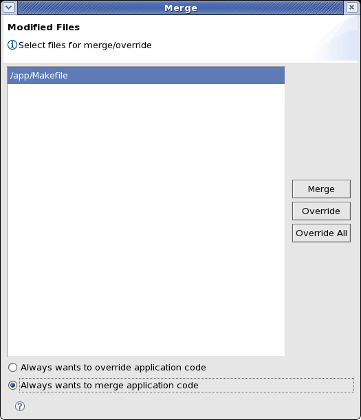
- Always override application code: Select this if you always want to overwrite existing model code with the code generated by the IDE. Note that with this setting you will lose any customization that you have made to IDE generated files.
- Always merge application code: Select this if you always want to merge newly generated source code with the existing model code. With this setting all code between the prede?ned begin/end application code blocks will be preserved during code generation.
4. Click OK. The properties for the project are set.
CHAPTER 3
Understanding the User Interface
This chapter provides information about the OpenClovis IDE work environment and helps you familiarize with its features.
Key Topics:
- Using Menu Bar
- Using Tool Bar
- Using OpenClovis Context Menu
- Using OpenClovis IDE Editor
- Viewing the Outline Plane
- Using Tasks,MIB File Explorer View, Error Log, Model Problems,Model template and Console Panes
- Adding New Blade Type
- Adding New Node
- Importing MIB Objects
- Migrating Project
3.1 Using Menu Bar
The Clovis menu and Project menu is available on the menu bar. Both the menu options can also be accessed using the right-click menu on a project listed under OpenClovis IDE Workspace.
3.1.1 Clovis Menu
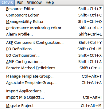
the Clovis Menu appear as
The options available are:
- Resource Editor: Use this option to display the Resource Editor.
- Component Editor: Use this option to display the Component Editor.
- Manageability Editor: Use this option to display the Manageability Editor.
- Performance Monitoring Editor: Use this option to display the Performance Monitoring Editor.
- Alarm Profile: Use this option to create alarm profiles required for your model.
- ASP Component Configuration: Use this option to specify the configuration parameters for the various ASP components.
- EO Definitions: Use this option to create the Memory configuration profiles.
- EO Configuration: Use this option to assign the memory configuration profiles to the various ASP and user-defined components.
- AMF Configuration: Use this option to specify the Availability Management Framework (AMF) parameters.*
- Remote Method Definitions: Use this option to define the Interface Definition Language (IDL) and the user-defined data types.
- Manage Template Group: Use this option to create the template groups.
- Associate Template Group: Use this option to associate the template group(s) to the components.
- Import Applications: Use this option to import applications into IDE model.
- Import Mib Objects: Use this option to import a MIB file allowing the defined components to be used in the model.
- Migrate Project: Use this option to migrate a project created under an older version of the IDE to the current version.
3.1.2 Project Menu
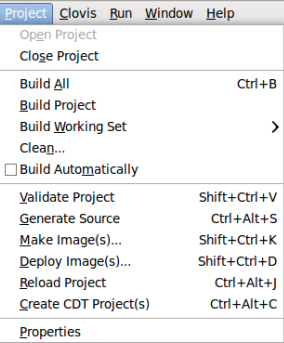
The Project menu is as shown.
The options available are:
- Open Project: Use this option to open the selected project.
- Close Project: Use this option to close the selected project.
- Build All: Use this option to build the ?nal project executable ?le for all the projects.
- Build Project: Use this option to build the ?nal project executable ?le for the selected project.
- Clean: Use this option to clean the selected project before building the executable.
- Validate Project: Use this option to check the selected model for errors.
- Generate Source: Use this option to generate sourc code for the selected model.
- Make Image(s): Use this option to create deployment images of the model.
- Deploy Image(s): Use this option to deploy the images created with previous option.
- Reload Project: Use this option to reload the project from disk.
- Create CDT Project(s): Use this option to create CDT projects for each applications.
- Properties: Use this option to specify the properties for the selected project.
3.2 Using Tool Ba
The add-on icons for the OpenClovis platform are as shown
3.3 Using OpenClovis Context Menu
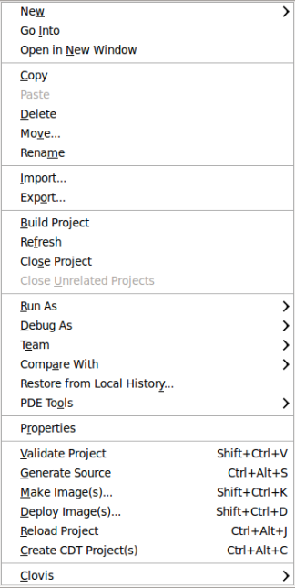
To display the OpenClovis context menu, right-click on a project in the Clovis Workspace pane. The OpenClovis context menu is displayed.
It has the following OpenClovis-related options
- New: Select the Project option to create a new OpenClovis project.
- Go Into: Goes to the next level of the project hierarchy.
- Open in New Window: Opens the selected resource in a new window.
- Copy: Places a copy of the selection on the clipboard.
- Paste: Inserts resources from the clipboard to the Clovis Workspace.
- Delete: Removes the current selection from the Workspace.
- Move: Moves resources from one Work bench location to another(for example, from one project to another project).
- Rename: Renames the selected resource.
- Import: Launches a wizard that allows you to import the following into the Clovis Workspace
- Archive File
- Checkout projects from CVS
- Existing Project into Workspace
- External Features
- External Plug-ins and Fragments
- File system
- Preferences Team
- Project Set
- Export: Launches a wizard that allows you to export the following from the Clovis Workspace (see note below):
- Ant Build Files
- Archive File
- Deployable features
- Deployable plug-ins and fragments
- Eclipse Product
- File system
- JAR file
- Java doc
- Preferences
- Team Project Set
- Build Project: Builds the project.
- Refresh: Refreshes the contents of the Clovis Workspace.
- Close Project: Closes a project.
- Properties: Displays a window showing all the property details of the current selection, such as path, type, location, and last modi?ed.
- Validate Project: Validates the project. Generate Source: Generates the source code for the project.
- Make Image(s): Use this option to create deployment images of the model.
- Deploy Image(s): Use this option to deploy the images created with previous option.
- Reload Project: Reload the project if any changes are done to the model ?les.
- Create CDT Project(s): Use this option to create CDT projects for each applications.
- Clovis: This cascading menu has various options which are inherent to OpenClovis IDE.
The other menu items like Team, Debug As, Run As, and so on are not applicable to OpenClovis IDE.
![]() If the selected project is older than the current version of IDE then all the clovis specific options are disabled in menu bar and toolbar except ’Migrate Project’. You must migrate the project to the latest version in order to use all the clovis specific options in menu bar and toolbar.
If the selected project is older than the current version of IDE then all the clovis specific options are disabled in menu bar and toolbar except ’Migrate Project’. You must migrate the project to the latest version in order to use all the clovis specific options in menu bar and toolbar.
![]() When using the Export utility you may encounter an error indicating that resources are out of sync. To avoid this problem you need to configure the work space to refresh automatically. Do this by going to the ’Window | Preferences...’ dialog, navigating to the ’General –> Works pace’ pane, and clicking the check box titled ’Refresh automatically’. After applying this setting you should not longer receive the error
When using the Export utility you may encounter an error indicating that resources are out of sync. To avoid this problem you need to configure the work space to refresh automatically. Do this by going to the ’Window | Preferences...’ dialog, navigating to the ’General –> Works pace’ pane, and clicking the check box titled ’Refresh automatically’. After applying this setting you should not longer receive the error
3.4 Using OpenClovis IDE Editors
OpenClovis IDE has two editors that allow you to model the resources and components.
The two editors are:
- Resource Editor
- Component Editor
- Manageability Editor
- Performance Monitoring Editor
Resource and Component editors support scalable views of the class models to improve usability if you create a large model. All the objects are arranged row by row. The position for each object is based on the parent position. For example, if the parent object is placed in the first row, the child object is placed in the second row. Connection points for all edges will be rearranged based on the location of the source and target objects.
You can automatically arrange all the objects in the editors to provide a better layout. To do this, right-click in the Resource Editor or Component Editor, and click Auto Arrange. The objects are re-arranged
You can also collapse or expand the child objects that belong to a parent object. To collapse the child objects, right-click on the object and select Collapse. To expand the child objects, right-click on the object and click Expand.
In the Resource Editor you can create managed resources that are not related to any given blade or node and are directly linked to the chassy. For example, a distributed system consisting of many blades has some provisioned information that is system-wide and requires access from applications that reside on many blades.
3.4.1 Using Resource Editor
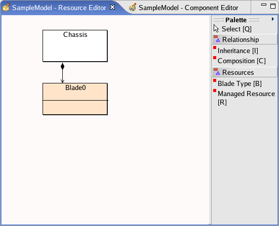
The Resource Editor is automatically displayed for a newly created project. A Resource Editor, by default, has a Chassis as a resource and helps you to:
- Model the physical resources existing on a system.
- Drag and drop(or use keyboard shortcut)to create all the resources to be managed using UML notations.
- Double-click a resource to de?ne its properties.
- Specify the attributes Provisioning, Chassis Management, and so on.
- Use a set of default, tailor-made resources in a Palette.
- Use relation connectors to de?ne the relationship between the resources.
3.4.1.1 Resource Editor Palette
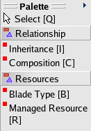
The Resource Editor Palette is displayed on the right side of the Resource Editor pane, when you select the Resource Editor tab. This Palette helps you to model there sources and de?ne the relationship between there sources. The Palette comprises the following options with the keyboard shortcuts speci?ed in brackets
- Relationship
- Inheritance [Shift + I]
- Composition [Shift + C]
- Resources
- Blade Type [Shift + B]
- Managed Resource [Shift + R
Space makes the editor go back to the Select mode.
The following table provides the representation of the various resource objects in UML in the Resource Editor.
| Resource Object | UML Representation |
| Blade Type | 
|
| Managed resource | 
|
Relationships:
- Inheritance relationship indicates that one resource is created from another and therefore contains certain common features with the parent resource. Inheritance links generalized classes to their specializations. To create inheritance relationship between resources, click Inheritance in the Palette (or use keyboard shortcut) and create connection from one resource to another resource to inherit the pre-defined properties. The derived resource inherits only the attributes and not the alarms.
- Composition relationship is a relationship where one resource consists or contains the other resource. To create Composition relationship, click Composition in the Palette (or use keyboard shortcut) and create connection from one resource to another resource. From a Physical perspective, a Chassis contains Blade Types that in turn, may contain Managed Resources.
3.4.1.2 Creating a Resource
You can create resources using the Resource Editor Palette or the Add New Blade wizard. To create a resource using the Resource Editor Palette:
- Click any Resource in the Palette.
- Drag the cursor onto the Resource Editor area. The cursor has an additional rectangle and + symbol,indicating that you are ready to create a Resource class model in Editor.
- Drop the object in the Resource Editor area. The object is displayed in the Editor. You can specify the name and set the properties for the resource by double clicking on it or by doing right click on it and selecting Properties.
3.4.2 Using Component Editor
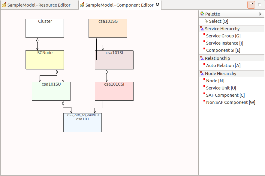
The Component Editor is automatically opened for a newly created project. Component Editor is primarily designed to cater to SAForum speci?cations and helps you to:
- Define a logical view between all resources that are modeled in the Resource Editor.
- Make associations with the defined resources.
The Component Editor by default always contains a Cluster. A Cluster is the entire system, containing multiple nodes.
A component is the smallest logical entity on which a fault recovery can be performed. The component could be a process, many processes or hardware. It represents a set of resources to the Availability Management Framework (AMF). The resources represented by the component encapsulate specific application functionality. This set can include hardware resources, software resources, or combinations of the two.
In the Clovis Workspace, a component is classified as a SA Forum Component or a Non-SA Forum Component.
3.4.2.1 Component Editor Palette
The Component Editor Palette is displayed on the right side of the Component Editor pane. This Palette helps you to model the components and define the relationship between the components.
To add an object (Node, SU, or Component) to the Component Editor, click the object in the palette and drag and drop (or use keyboard shortcut) the object in the Component Editor pane.
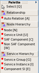
The Palette comprises the following options with the keyboard shortcuts specified in brackets:
- Relationship
- Auto Relation [Shift + A]: drops a relationship edge between the components based on the type.
- Node Hierarchy
- Node [Shift + N]: is the logical representation of a physical node.
- Service Unit [Shift + U]: is a logical entity that aggregates a set of components combining their individual functionalities to provide a higher level service.
- SAF Component [Shift + C]: is the smallest logical entity on which the Availability Management Framework performs error detection and isolation, recovery, and repair.
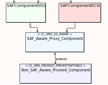
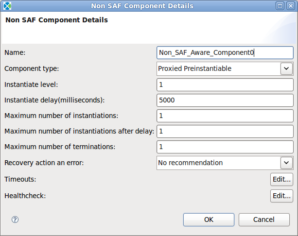
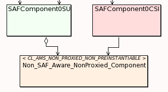
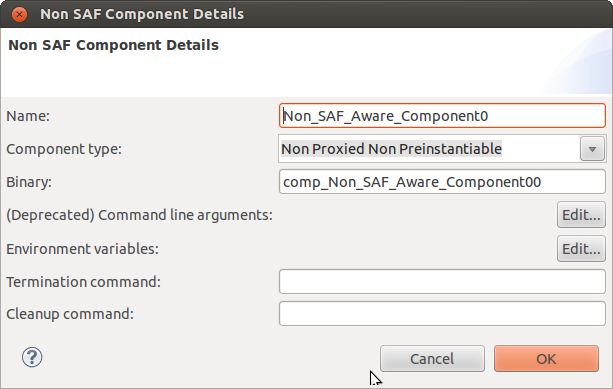
- Non-SAF Component[Shift+W]: are components that do not register directly with the Availability Management Framework. These components can be either Proxied or Non-Proxied depending on how they are associated with other objects in the editor. See Setting Non-SA Forum Component Details for more details.
- Service Hierarchy
- Service Group [Shift + G]: is a logical entity that groups one or more service units to provide service availability for a particular set of service instances.
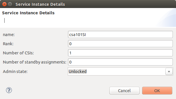
- Service Instance [Shift + I]: is the aggregation of component service instances.
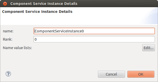
- Component Service Instance [Shift + E]: represents the workload that the Availability Management Framework can dynamically assign to a component.
![]() Assigning multiple name value pairs same CSI type will not be possible with current IDE.
Assigning multiple name value pairs same CSI type will not be possible with current IDE.
The following table provides the UML representation of the various component objects in the Component Editor:
| Component Object | UML Representation |
| Node | 
|
| Service Unit | 
|
| SA Forum Component | 
|
| Non-SA Forum Component | 
|
| Service Group | 
|
| Service Instance | 
|
| Component Service Instance | 
|
3.4.2.2 Creating a Component
You can create components using the Component Editor Palette or the Add New Node wizard.
To create a component using the Component Editor Palette:
- Click any component in the Palette .
- Drag the cursor onto the Component Editor area. The cursor has an additional rectangle and + symbol, indicating that you are ready to create a Component in Editor.
- Drop the object in the Component Editor. The object is displayed in the Editor.
You can specify the name and set the properties for the component by double clicking on it or by doing right click on it and selecting Properties.
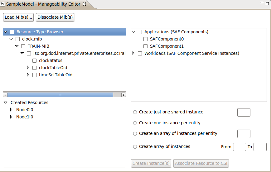
3.4.3 Using Manageability Editor
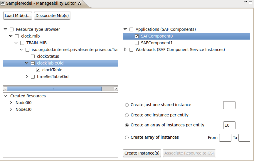
This editor helps you to associate whole/part of MIB to Componet. Also IDE will automatically creates instances for the associated resources.
To open Manageability Editor, click Clovis -> Manageability Editor.
Manageability Editor has Resource Type Browser, Created Resources tabs:
- Resource Type Browser helps you to Load MIBs and view Loaded MIBs in hierarchical tree also helps to select whole or part of MIBs.
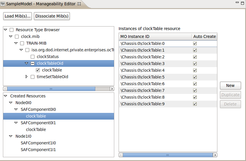
- Created Resources helps you to view already created resources.
3.4.3.1 Associating Resources with Component
- Select a particular node/individual resource in the Resource Type Browser on left pane (this resource and all children are selected). Also, you may shift-click to select multiple resources.
- Select a particular Component or multiple Components in the right pane. Again, you may shift click to select multiple Components.
- Select either Create instance or Create group of instances radio button, and ?ll out the array of instances if desired. If you ?ll out Create array of instances per entity as 10, You’ll be creating resource instance :1 :2 :3 :4...... :10.
4.Click Create Instance(s) button.
Every selected resource will be instantiated (multiple times if a range or multiple instances are specified),in every selected component. If you then open up the Created Resources tree,You’ll be able to see these newly instantiated resources. Also You’ll be able to see the created resource instances in the right pane by selecting resource type in Created Resources tree.
3.4.4 Using Performance Monitoring Editor
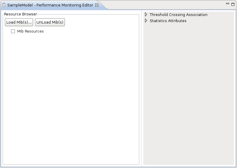
The Performance Monitoring Editor can be opened/displayed by selecting Performance Monitoring Editor option from Clovis Menu or ToolBar. It can also be launched with keyboard shortcut Shift+Ctrl+P.
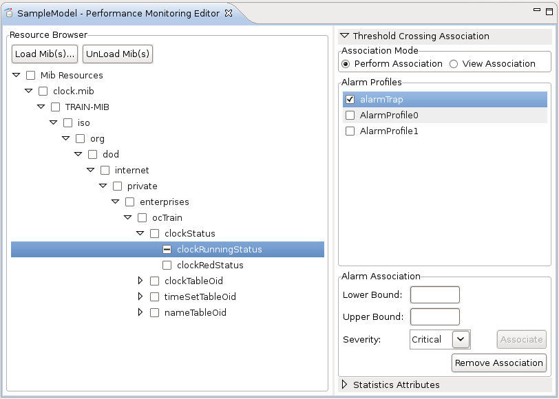
It has Resource Browser,Threshold Crossing Association and Statistics Attributes sections and helps you to:
- Browse multiple Mib files with Resource Browser.
- Perform alarm association,view already configured alarms and remove alarm association with Threshold Crossing Association.
- Configure lower bound, upper bound and severity for alarm association with Threshold Crossing Association.
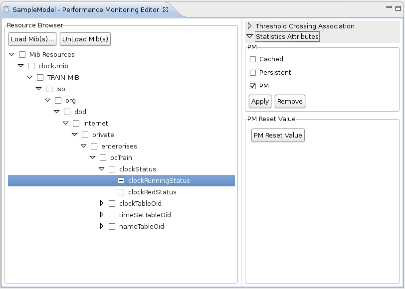
- Mark/Unmark various statistics such as Cached, Persistent and PM for attributes.
- Configure PM Reset Value for bunch of PM attributes.
3.4.4.1 Resource Browser
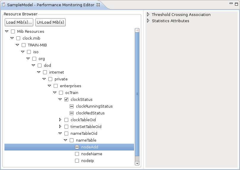
The Resource Browser allows to browse resources and attributes from mib files. User can select/deselect resources/attributes from resource browser for various PM configurations. There is a check box provided for each resource/attribute to check them. If user selects/deselects some entry then all the child entries are selected/deselected automatically. User can check multiple resources/attributes to do similar configuration for them in bulk.
- Load Mib(s): allows to load mib into the resource browser. Clicking on it, File selection dialog opens up. Select the mib file, you want to open up with the resource browser. All the resources/attributes from the mib are shown in the resource browser.
- UnLoad Mib: will unload the selected mib. All the resources/attributes of the mib will be removed from the resource browser.
3.4.4.2 Threshold Crossing Association
The Threshold Crossing Association allows user to configure alarms for attributes. It also allows to see the already configured alarm for particular attribute.
- Association Mode: There are to association modes,
- Perform Association: If this mode is selected then user can configure the alarms with selected attributes.
- View Association: If this mode is selected then user can view the currently configured alarms for the attributes. User has to select the attribute in the resource browser to see the alarm configuration for the same.
- Alarm Profiles: This will show all the alarm profiles available for the model. There is a check box provided with each alarm profile name. User can select the check box to con?gure that particular alarm to the attributes selected from the resource browser. User can select only a single alarm from this list. When user selects a new alarm then earlier selection is automatically cleared.
- Alarm Association: This section allows to configure various parameters for alarm association, associate alarm and remove alarm association.
- Associate: This will associate the selected alarm from the alarm pro?le list to the selected attributes from the resource browser. The same alarm will also be configured for the parent resource of the selected attribute.
- Lower Bound: Specifies the lower bound for the alarm association.
- Upper Bound: Specifies the upper bound for the alarm association.
- Severity: Specifies the severity for the alarm. Available options are Critical, Major, Minor and Warning.
- Remove Association: This will remove the association for the selected alarm from the selected attributes. (For already associated alarms)
- Associate: This will associate the selected alarm from the alarm pro?le list to the selected attributes from the resource browser. The same alarm will also be configured for the parent resource of the selected attribute.
3.4.4.3 Statistics Attributes
The Statistics Attribute section allows user to configure various attribute statistics and configure PM Reset Value.
- PM: User can mark the selected attributes as Cached, Persistent and/or PM by selecting the statistics and licking Apply. User can unmark the statistics in the same way by clicking Remove.
- PM Reset Value: To configure the Reset value, select the bunch of PM attributes from the same resource for which you want to configure the reset value. Click on PM Reset Value button. This will show up all the the possible attributes that can be configured as Reset value for that bunch of attributes. Select any attribute from the displayed attributes and click on Apply. Confirmation message is given after the PM Reset Value is configured.
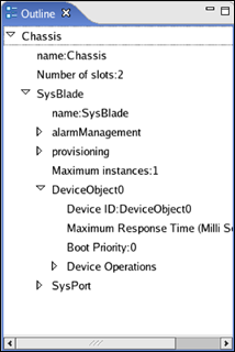
3.5 Viewing the Outline Pane
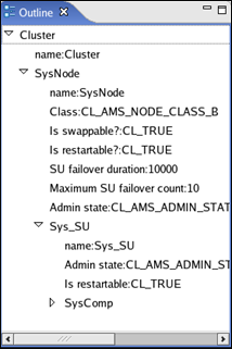
The Outline pane represents the hierarchical relationships of the resources and the components on the respective tabs.
To open the outline pane:
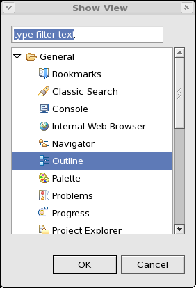
1. From the Window menu, point to Show View, and click Other. The Show View dialog box is displayed.
2 . Click General, select Outline, and then click OK or type Outline in the text box. The Outline pane is displayed
![]() To restore the default display of OpenClovis IDE, from the Window menu, select Reset Perspective.
To restore the default display of OpenClovis IDE, from the Window menu, select Reset Perspective.
3.6 Using Tasks, MIB File Explorer View, Error Log, Model Problems, Model Template, and Console Panes
At the bottom of the OpenClovis IDE window, by default, the following panes are displayed:
- Tasks
- MIB File Explorer
- Error Log
- Model Problems
- Model Template
- Console
3.6.1 Tasks
The Tasks pane is not used within the OpenClovis IDE functionality.
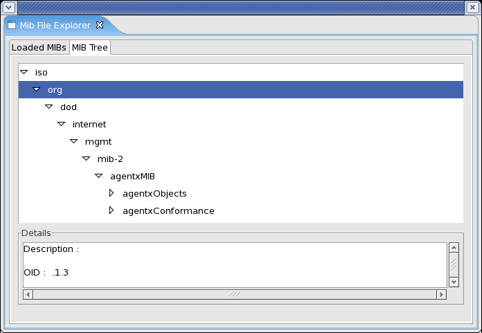
3.6.2 MIB File Explorer
MIB File Explorer is a utility used to load multiple MIBs in a sequence in the model.
MIB File Explorer has two tabs:
- Loaded MIBs:: This tab is used to load external 3rd party MIBs or Clovis MIBs into the model and subsequently use its attributes for the model. To load a MIB,click Load. Select some MIB files. Loaded MIBs Tab will display following information for the Loaded MIB files:
- MIB Name : Name of the MIB.
- Number of Nodes : Number of nodes in the MIB.
- MIB Size : Size of the MIB.
- MIB Path : Path from where the MIB is imported.
- Description : Description of the MIB. Click Unload to unload the MIB.
- MIB Tree : This tab helps to expand the loaded MIB in the form of a tree structure.
The MIB tree is a structure that groups MIB objects in a hierarchy and uses an abstract syntax notation to define manageable objects. Each item on the tree is assigned a number, which creates the path to objects in the MIB. This path of numbers is called the Object Identifier (OID). Each object is uniquely and unambiguously identified by the path of numeric values.
If you close the MIB File Explorer pane,you can display it again. To dot his,from the Window menu, point to Show View , and then click Other. The Show View dialog box is displayed. Double-click Clovis, select MIB File Explorer, and then click OK.
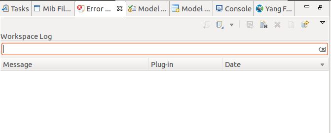
3.6.3 Error Log
The Error Log pane maintains a log of all the errors that are encountered while modeling. These errors are raised by Eclipse platform and the OpenClovis IDE. These may be errors due to problems in Eclipse or errors detected by OpenClovis IDE during modeling.
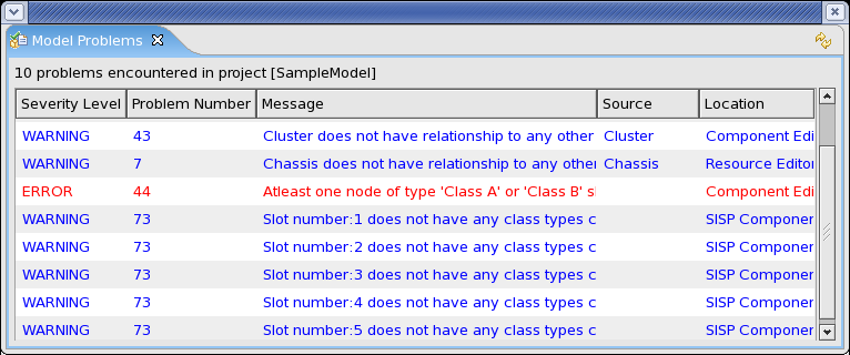
3.6.4 Model Problems
The Model Problems pane displays the errors warnings as you model the project. To resolve the error, right-click on the error message, point to Auto Correction Options , and then select the required correction to be performed. OpenClovis IDE resolves the error automatically.
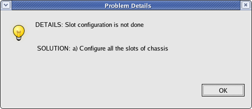
To view the error details, right-click on the error message, and click Details. The Problem Details window is displayed. It provides the details about the error message and the solution for the problem to resolve the error.
![]() For some error messages, the Auto Correction Option is not available. In this case, you have to resolve the error manually as per the solution provided in the Problem Details window.
For some error messages, the Auto Correction Option is not available. In this case, you have to resolve the error manually as per the solution provided in the Problem Details window.
Double-clicking on the error message highlights the object causing the error or displays the dialog where you need to ?x the error.
If you close the Model Problems pane, you can display it again. To do this, from the Window menu, point to Show View , and then click Other. The Show View dialog box is displayed. Double-click Clovis, select Model Problems, and then click OK. Refresh the pane to view the updated list of errors.
3.6.5 Model Template
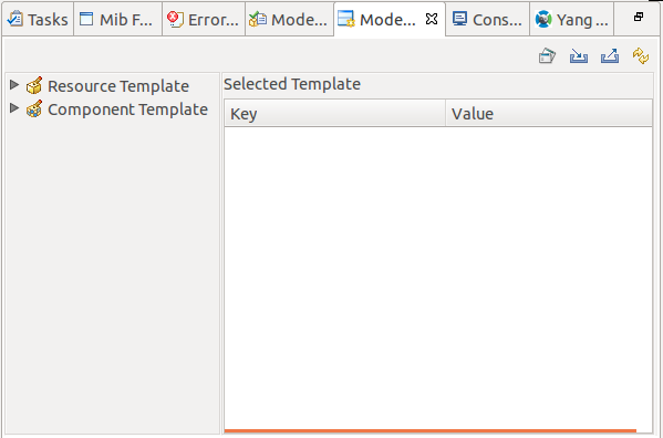
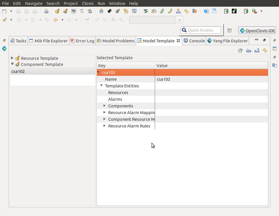
You can select resources from the Resource Editor / components(applications) from the Component Editor and save them as custom templates. These templates appear in the Model Template tab. These templates can be reused for creating resource or component trees inside IDE Editor for other projects.
A view is provided for you to manage the model templates and see its structure. To view the structure, select the template from the view and its structure appears under Selected Template. All available templates are shown as a list in left hand side portion of the view.
You can perform the following:
- Use the Model Template
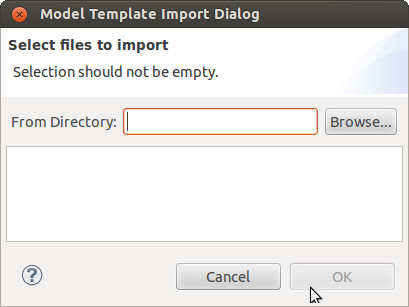
- Import Model Template
- Export Model Template
- Refresh Model Template
View For more information, see Chapter Model Templates .
3.6.6 Console
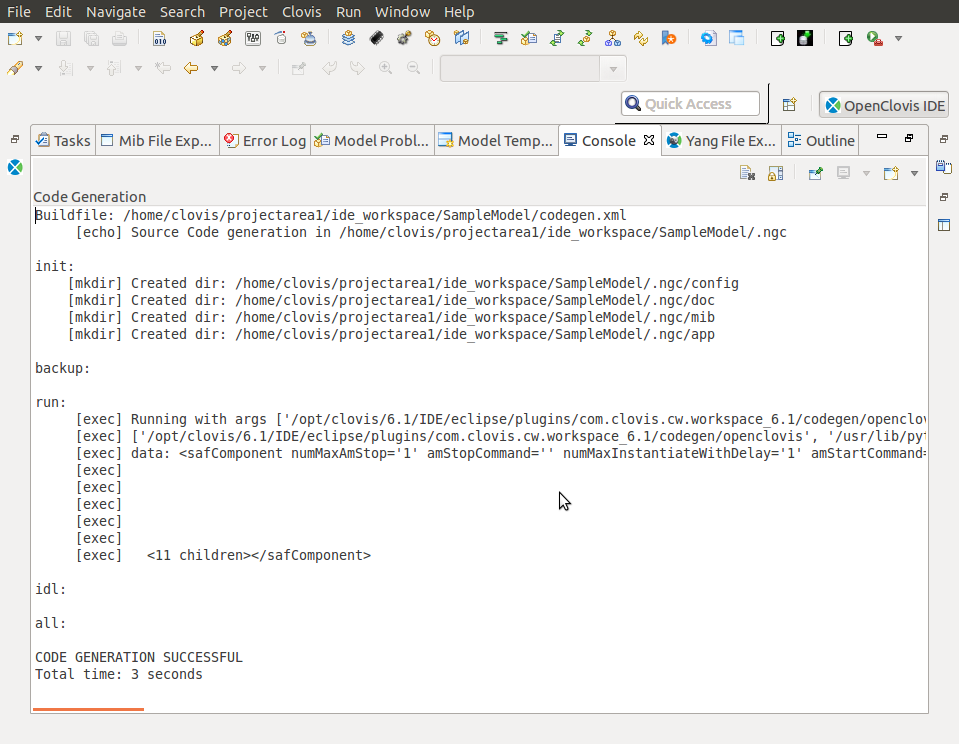
The Console pane is activated when you perform certain actions on the project (e.g. generating code,building the project, etc.) It displays diagnostic information about the progress of the action and displays warnings and errors if they occur. Finally it displays the success or failure of the action.
If you close the Console pane, you can display it again. To do this, from the Window menu, point to Show View, and then click Other. The Show View dialog box is displayed. Double-click Basic, select Console, and then click OK.
3.7 Adding New Blade Type
You can use the Add New Blade Type wizard to add a blade type along with the managed resources that it is composed of. To do this:
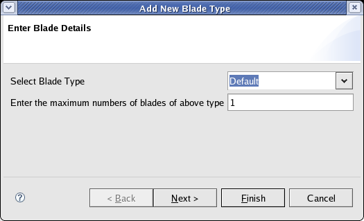
1. Right-click on the Resource Editor and select Add New Blade Type. The Add New Blade Type wizard is displayed.
2. Enter the information for the following:
- Select Blade Type: Select the type of the blade from the drop-down list.
- Enter maximum numbers of blades of the above type: Number of blades of the selected type to be added to the Resource Editor.
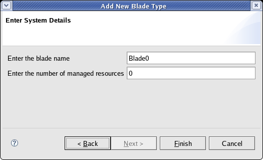
3. Click Next. The Enter System Details window is displayed.
4. Enter the following information:
- Enter the blade name: Name of the new blade type.
- Enter the number of managed resources: Number of resources belonging to the blade.
5. Click Finish. The added resource appears in the Resource Editor.
3.8 Adding New Node
You can add a node, specify the number of SA aware components, and associate resources to the components using the Add New Node wizard. To do this:
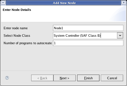
1. Right-click on the Component Editor and select Add New Node. The Add New Node wizard is displayed.
2. Enter the information for the following:
- Enter Node Name: Name of the new node.
- Select Node Class: Type of class to which the new node belongs.
- Number of programs to auto create: Enter the number of programs (SAF Service Types) to create for this new node.
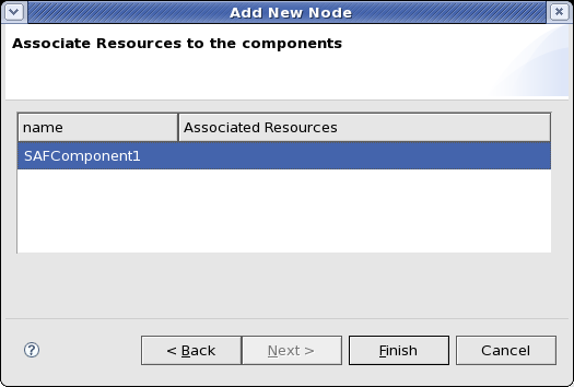
3. Click Next. The Associate Resources to the components window is displayed. The specified number of SA Forum components are listed for which resources need to be associated.
4. Enter the information for the following:
- Name: Enter the root name of the SAF Service Type. This name will be used for the created component and also as the root for all of the associated SAF entities (Service Group, Service Unit, etc.).
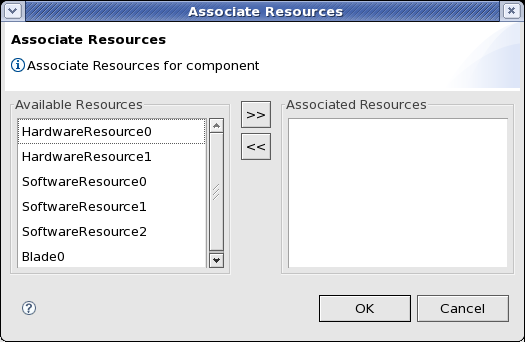
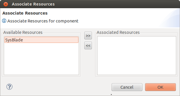
5. Set focus to the Associated Resources column and click Edit. The Associate Resources window is displayed.
6. Select the resources for the component and click >> to move them under Selected Resources. 7. Click OK and then click Finish. The new node and any defined programs appear in the Component Editor.
3.9 Importing MIB Objects
You can import MIB objects as resource classes. You can load a MIB and then select appropriate tables for import.
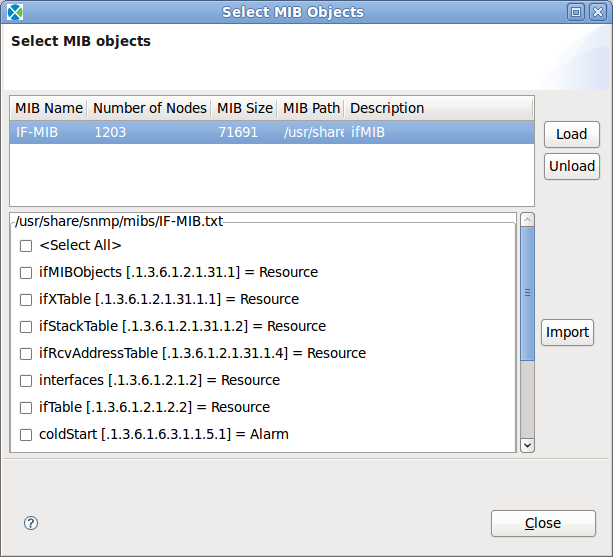
To import a MIB Object, from the Clovis menu, select Import Mib Objects or click the Import Mib Objects icon on the toolbar. The Select MIB Objects dialog box is displayed.
Click Load to load external 3rd party MIBs or Clovis MIBs into the model and subsequently use its attributes for the model.
Click Unload to unload the MIB.
Select tables and notifications in the lower pane of the dialog and click Import to load the selected MIB objects into the model.
![]() If the MIB is dependent on other MIBs, they must be present in the same directory or else error occurs. After the selection is done, the tables become software resource classes with provision-able attributes corresponding to the table columns. All scalars are consolidated into a separate SW resource class. Each notification in the MIB will be imported as alarm. The imported MIB objects are grouped together in the Resource Editor in a virtual container for ease of use.
If the MIB is dependent on other MIBs, they must be present in the same directory or else error occurs. After the selection is done, the tables become software resource classes with provision-able attributes corresponding to the table columns. All scalars are consolidated into a separate SW resource class. Each notification in the MIB will be imported as alarm. The imported MIB objects are grouped together in the Resource Editor in a virtual container for ease of use.
3.10Migrating Project
When a new version of the IDE is released you can migrate your existing projects to this new version. The IDE detects the version of the existing project and transforms the internal structures to conform with the new version. It also provides an option to create a backup of the project while performing the migration.
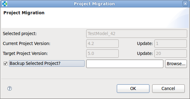
To migrate a project, from Clovis menu, click Migrate Project or click on the Migrate Project icon on the toolbar. The Migrate Project dialog box is displayed.
The information is displayed by default for the following fields:
- Selected Project: The project that will be migrated.
- Current Project Version: The version of project to be migrated.
- Target Project Version: The version to which the project will be migrated.
- Backup the selected project?: Select this check box if you need to create a backup of the project that you will be migrating. The Browse button and accompanying text box will become enabled allowing you to select the location where the backup should be created.
![]() If you wish to revert back to the backup version at a later time you should use the project import functionality to import the backed up model into the work space.
If you wish to revert back to the backup version at a later time you should use the project import functionality to import the backed up model into the work space.
Click OK. The project is migrated to the current version.
CHAPTER 4
Setting Resource Properties
This chapter provides information about the properties that you can specify for the chassis, node hardware, hardware, and software resources in the Resource Editor.
Key Topics:
- Setting Chassis Properties
- Setting Blade Type and Managed Resource Properties
For information about creating a resource, see Chapter [[Understanding the User
Interface.]]
4.1 Setting Chassis Properties
To set the properties for the Chassis:
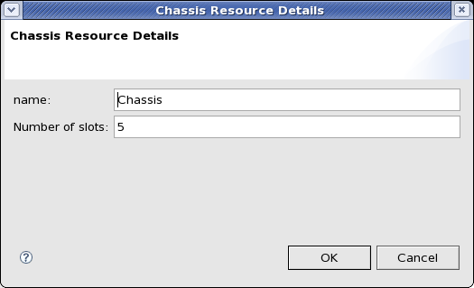
1. Right-click on the Chassis resource and select Properties or double-click the Chassis resource. The Chassis Resource Details window is displayed.
2. Enter the following information:
- Name : Name for the Chassis.
- Number of slots : Number of slots present in the chassis.
3. Click OK. The properties are saved.
4.2 Setting Blade Type and Managed Resource Properties
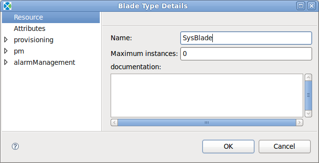
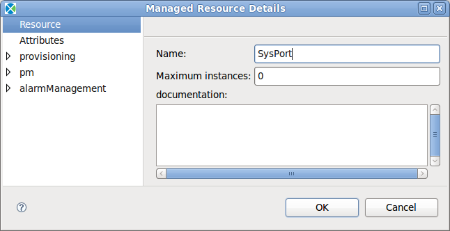
To set the properties for a resource, right-click on the resource and select Properties or double-click the resource. The Blade Type Details or Managed Resource Details window is displayed depending on the resource selected.
The following illustrations show the Blade Type Details and Managed Resource Details windows.
You can perform the following for a Blade Type or Managed Resource:
- Specifying Resource Details
- Specifying Resource Attributes
- Specifying Provisioning Attributes
- Specifying Pm Attributes
- Enabling and Associating Alarms
![]() All the screens in this chapter are provided for a Managed Resource. If you are setting the properties for a Blade Type, the window title displays Blade Type Details.
All the screens in this chapter are provided for a Managed Resource. If you are setting the properties for a Blade Type, the window title displays Blade Type Details.
4.2.1 Specifying Resource Details
The Resource is selected, by default, in the Resource Details window.
Enter the following information:
- Name: Name of the resource.
- Maximum Instances:: Maximum instances of this resource. By default, the value is 1.
- Documentation: Enter any required information.
4.2.2 Specifying Resource Attributes
To specify the attributes for a resource:
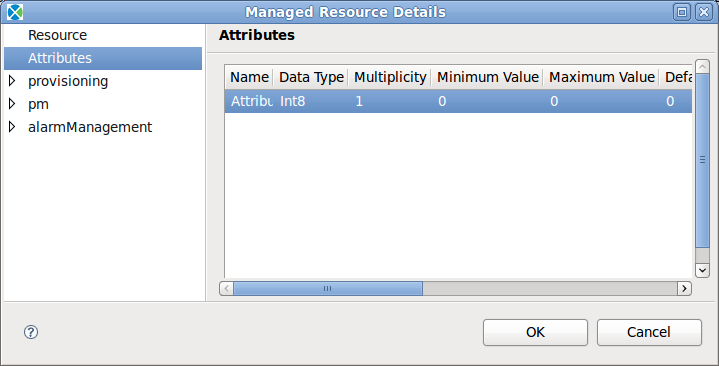
1. In the Resource Details window, click Attributes on the left-side. The Attributes pane is displayed on the right-side. This pane lists all the attributes that are defined for any resource. Click New to create a new attribute.
2. Enter the following information:
- Name: Name of the attribute.
- Date Type: Data type of the attribute. The options available are:
- Int8
- Uint8
- Int16
- Uint16
- Int32
- Uint32
- Int64
- Uint64
The following data types are SNMP supported data types, and are used in SNMP Import.
- OCTET STRING
- Gauge32
- Counter32
- Counter64
- TimeTicks
- IpAddress
- NetworkAddress
- Opaque
- UTF8String
- BITS
- IA5String
- TruthValue
- DisplayString
- INTEGER
- OBJECT IDENTIFIER
- Multiplicity:: Defines the number of elements in the array. Used only if the attribute is an array.
- Minimum and Maximum Value: This represents the range of values that can be used for the attributes. You can set a value within this range during runtime configuration for the attribute.
- Default Value: Define a default value between the range of min and max values. This default value is assigned to the corresponding attribute during system start up.
- Attribute Type: This represents if the attribute is configurable or transient attribute (also called run-time attribute.) The options available are:
- Config
- Run-time
Configurable attributes are attributes whose value can be set. Transient attributes are attributes whose value changes at run-time and are read-only attributes. The value of the transient attribute is not stored in COR but is get/set from the component that owns this attribute. For more information on configuration and transient attributes, refer OpenClovis SDK User Guide .
- Persistent : Select this checkbox to specify if the attribute needs to be persisted.
- Cached : Select this checkbox to specify if the attribute needs to be cached.
- Imported :Indicates whether the attribute is imported from an external MIB file or not. When you import an external MIB file, a tick mark appears in the checkbox. The imported attributes are used as the node attributes. They cannot be modified by the user.
- Writable : Select this checkbox to specify if the attribute is writable.
- Initialized : Select this checkbox if the attribute needs to be initialized.
3. Click Duplicate to create a duplicate attribute.
![]() Duplicity is applicable to all fields except the name. The name of the attribute must be unique.
Duplicity is applicable to all fields except the name. The name of the attribute must be unique.
4. Click Delete to delete a selected attribute. 5. Click Move Up to move the attribute up. 6. Click Move Down to move the attribute down. 7. Click Import to import attributes from any pre-defined MIB.
![]() Do not import the notification type objects from the MIB. OpenClovis IDE does not validate the type of objects being imported and an error is displayed.
Do not import the notification type objects from the MIB. OpenClovis IDE does not validate the type of objects being imported and an error is displayed.
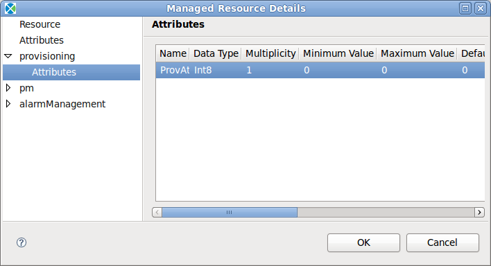
4.2.3 Specifying Provisioning Attributes
To specify provisioning attributes perform the following steps:
1. Double-click provisioning on the left-side and click Attributes. The Attributes pane lists all the provisioning attributes for a given resource. Click New to add a new provisioning attribute.
2. Enter the following information:
- Name: Name of the attribute.
- Type: :Indicates the data type of the attribute. The options available are:
- Int8
- Uint8
- Int16
- Uint16
- Int32
- Uint32
- Int64
- Uint64
The following data types are SNMP supported data types, and are used in SNMP Import.
- OCTET STRING
- Gauge32
- Counter32
- Counter64
- TimeTicks
- IpAddress
- NetworkAddress
- Opaque
- UTF8String
- BITS
- IA5String
- TruthValue
- DisplayString
- INTEGER
- Multiplicity: Defines the number of elements in the array. Used only if the attribute is an array.
- Minimum and Maximum Value:: This represents the range of values that can be used for the attributes. You can set a value within this range during runtime configuration for the attribute.
- Default Value::User defines a default value between the range of min and max values. This default value is assigned to the corresponding attribute during system start up.
- Attribute Type: This represents if the attribute is configurable or transient attribute. The options available are:
- Config
- Run-time Configurable attributes are attributes whose value can be set. Transient attributes are attributes whose value changes at run-time and are read-only attributes. The value of the transient attribute is not stored in COR but is get/set from the component that owns this attribute. For more information on configuration and transient attributes, refer OpenClovis SDK User Guide .
- Persistent: Select this checkbox to specify if the attribute needs to be persisted.
- Cached: Select this checkbox to specify if the attribute needs to be cached.
- Imported: Indicates whether the attribute is imported from an external MIB file or not. When you import an external MIB file, a tick mark appears in the checkbox. The imported attributes are used as the node attributes. They cannot be modified by the user.
- Writable: Select this checkbox to specify if the attribute is writable. *Initialized: Select this checkbox to specify if the attribute needs to be initialized.
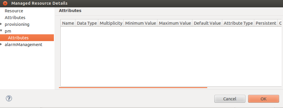
4.2.4 Specifying Pm Attributes
To specify pm attributes perform the following steps:
1. Double-click pm on the left-side and click Attributes. The Attributes pane lists all the pm attributes for a given resource. Click New to add a new pm attribute.
2. Enter the following information:
- Name: Name of the attribute.
- Type: :Indicates the data type of the attribute. The options available are:
- Int8
- Uint8
- Int16
- Uint16
- Int32
- Uint32
- Int64
- Uint64
The following data types are SNMP supported data types, and are used in SNMP Import.
- OCTET STRING
- Gauge32
- Counter32
- Counter64
- TimeTicks
- IpAddress
- NetworkAddress
- Opaque
- UTF8String
- BITS
- IA5String
- TruthValue
- DisplayString
- INTEGER
- Multiplicity: Defines the number of elements in the array. Used only if the attribute is an array.
- Minimum and Maximum Value:: This represents the range of values that can be used for the attributes. You can set a value within this range during runtime configuration for the attribute.
- Default Value::User defines a default value between the range of min and max values. This default value is assigned to the corresponding attribute during system start up.
- Attribute Type: This represents if the attribute is configurable or transient attribute. The options available are:
- Config
- Run-time Configurable attributes are attributes whose value can be set. Transient attributes are attributes whose value changes at run-time and are read-only attributes. The value of the transient attribute is not stored in COR but is get/set from the component that owns this attribute. For more information on configuration and transient attributes, refer OpenClovis SDK User Guide .
- Persistent: Select this checkbox to specify if the attribute needs to be persisted.
- Cached: Select this checkbox to specify if the attribute needs to be cached.
- Imported: Indicates whether the attribute is imported from an external MIB file or not. When you import an external MIB file, a tick mark appears in the checkbox. The imported attributes are used as the node attributes.They cannot be modified by the user.
- Writable: Select this checkbox to specify if the attribute is writable.
- Initialized: Select this checkbox to specify if the attribute needs to be initialized.
4.2.5 Associating Alarms
You have to define the alarms in the Alarm Profile window and then associate them to a resource and specify the generation rule for the alarm. For information about defining alarms, see Chapter 6 Defining Alarm Profiles. Association refers to associating the defined alarms to a particular resource. After associating the alarms to the resources, the generation rule has to be specified for the alarm to be generated.
To associate pre-defined alarms to a resource:
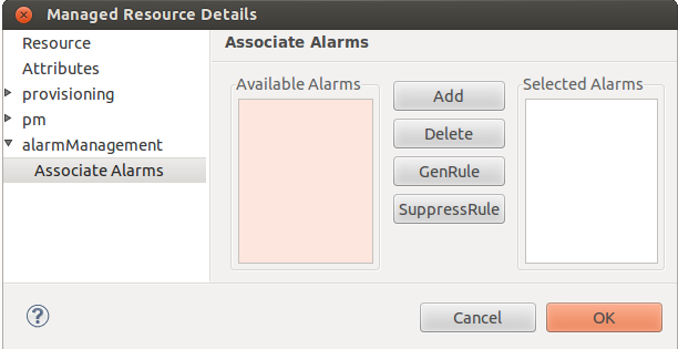
1. In the Resource Details window, double-click alarm Management and select Associate Alarms. The Associate Alarms pane is displayed on the right-side.
The alarms that are defined in the Alarm Profile window are listed under Available Alarms area.
2. Select the alarms that are applicable to this resource and click Add to move them under Selected Alarms for this resource.
![]() Two alarms with the same probable cause cannot be associated to the same resource.
Two alarms with the same probable cause cannot be associated to the same resource.
- Add: This associates an alarm from the existing list to a resource.
- Delete: This disassociates an alarm with a resource.
- GenRule: Click this button to create a rule that defines the condition under which the selected rule will be generated. An alarm that does not have a Generation Rule associated with it will never be raised.
- Suppress Rule: Click this button to create a rule that defines the condition under which the selected alarm will be suppressed.
For information about configuring the alarm rule, refer Configure Alarm Rule section.
Corresponding to the application that is managing the resource, the code for the associated alarms are generated in the cl<component_name>alarm-MetaStruct.c file located in the <projectarea_directory>/<model_name>/src/app/<component_name>/ directory.
4.2.5.1 Configure Alarm Rule
After you select the alarms that are to be associated with the resources you have to specify the alarm rule for the alarms to be raised/suppressed. The alarm rule can be a generation or a suppression rule. An alarm cannot be generated, if the alarm rule is not specified. Generation rule provides a mechanism to specify constraints on generation of alarms. Suppression rule specifies constraints on the suppression of alarms.
You can also specify a generation rule to model dependencies between alarms. A generation rule specifies the following:
- Alarm to be generated
- Dependent alarms
- Condition that has to be satisfied for the alarm to be generated. This condition is specified as a logical relationship between the dependent alarms.
A suppression rule specifies the following:
- Alarm to be suppressed
- Dependent alarms
- Condition that needs to be satisfied for the alarm to be suppressed. This condition is specified as a logical relationship between the dependent alarms.
An alarm rule can have a maximum of four alarms in an Alarm rule. An alarm rule can either have logical OR or logical AND operators but not both.
You can configure alarms in the Associate Alarms window.
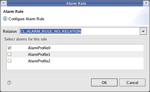
Select the alarm for which you need to configure the generation rule/suppression rule and click GenRule or SuppressRule. The Alarm Rule dialog box is displayed.
From the Relation drop-down list, select the relation. Three relations are available:
CL_ALARM_RULE_NO_RELATION
CL_ALARM_RULE_LOGICAL_OR
CL_ALARM_RULE_LOGICAL_AND
Select the alarm(s) for which you need to apply the generation rule and click OK.
If you choose CL_ALARM_RULE_NO_RELATION, then you need to check only one of the alarms present under Select alarms for this rule. This alarm is the same alarm for which the generation rule/suppression rule is applied, that is the alarm that you selected under Selected Alarms while associating the alarms (in Figure Associate Alarms).
However, if you choose any of the other two relations, then you can select more than one alarm. Selected alarm should not be the same alarm for which the generation rule/suppression rule is applied, that is the alarm that you selected under Selected Alarms while associating the alarm (in Figure Associate Alarms).
CHAPTER 5
Defining Alarm Profiles
This chapter provides information about defining alarms to map to the resources. Any application can raise an alarm, on detecting an erroneous condition on a managed resource. You have to pre-define the variety of alarms to be raised in a system for different categories, probable causes, and severity types. All the categories and probable causes conform to the ITU-T X.733 standard. For each category, there is a different set of probable causes.
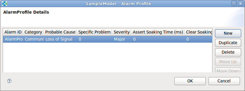
1. The alarms are defined in the Alarm Profile window. From the Clovis menu, click Alarm Profile... or press Shift+Ctrl+L on the keyboard to open the Alarm Profile window.
2. To create an alarm profile, click New and enter the following:
- Alarm ID : This is the alarm ID.
- Category : Category to which the alarm belongs. Select the Category of the alarm from the list.
- Probable Cause : Probable causes for the alarm to be activated. Select the Probable Cause of the alarm from the list.
The following table lists the available categories and the probable causes for each of the categories.
| Category | Probable Cause
|
| Communications | Loss of signal
Loss of frame Framing error Local node transmission error Remote node transmission error Call establishment error Degraded signal Communications subsystem failure Communications protocol error LAN error DTE
|
| Quality of service | Response time excessive
Queue size exceeded Bandwidth reduced Retransmission rate excessive Threshold crossed Performance degraded Congestion Resource at or nearing capacity
|
| Processing error | Storage capacity problem
Version mismatch Corrupt data CPU cycles limit exceeded Software error Software program error Software program abnormally terminated File error Out of memory Underlying resource unavailable Application subsystem failure Configuration or customization error
|
| Equipment | Power problem
Timing problem Processor problem Dataset or modem error Multiplexer problem Receiver failure Transmitter failure Receive failure Transmit failure Output device error Input device error Input output device error Equipment malfunction Adapter error
|
| Environmental | Temperature unacceptable
Humidity unacceptable Heating or ventilation or cooling system problem Fire detected Flood detected Toxic leak detected Leak detected Pressure unacceptable Excessive vibration Material supply exhausted Pump failure Enclosure door open |
- Severity: Select the Severity of the alarm from the list. The available options are:
1.Critical
2.Major
3.Minor
4.Warning
- Specific Problem: An integer value providing more specific information about the alarm being raised.
- Assert Soaking Time (Milliseconds): This is the time during which the alarm is observed before actually raising it as a genuine alarm.
- Clear Soaking Time (Milliseconds): This is the time when the alarm is cleared.
- Description: Enter any description for the alarm.
![]() The alarm will be raised/cleared after the time interval specified in the Assert Soaking Time/Clear Soaking Time fields, for that particular alarm. If you want to raise the alarm instantly then the values of both the fields has to be 0.
The alarm will be raised/cleared after the time interval specified in the Assert Soaking Time/Clear Soaking Time fields, for that particular alarm. If you want to raise the alarm instantly then the values of both the fields has to be 0.
3. Click OK. The alarms are saved.
CHAPTER 6
Setting Component Properties
This chapter provides information about the properties that you can specify for the various components in the Component Editor.
Key Topics:
6.1 Setting Cluster Details
A cluster is a collection of nodes that have the following characteristics:
- Nodes have been configured as members of the cluster.
- The corresponding physical nodes provide adequate support to run their application processes.
- All nodes are capable of communicating with each other.
- All nodes are managed by a single Availability Management Framework
Double-click the cluster or right-click on the cluster and select Properties. The Cluster Details window is displayed.
Enter the name for the cluster and click OK. The cluster name is saved.
6.2 Setting Node Details
A node is a blade, a stand-alone PC, or a daughter card that runs the AIS services and can become a member of the cluster. For more information, refer Service Availability Forum Overview Document on the SA Forum Web site (www.saforum.org.)
Double-click the Node or right-click on the Node and select Properties. The Node Details window is displayed.
Figure 6.2: Node Details
Enter the following information:
- Name: Name of the node. This is a unique identifier.
- Class: Select one of the following options from the drop-down list: (For infor-mation about these options, refer Glossary)
- System Controller
- Payload
- Is swappable?: Specifies if the blade is removable or irremovable. Select the True or False option from this list. True indicates that the blade is removable.
- Is restartable?: Specifies if the Service Unit can be restarted. Select the True or False option from this list. True indicates that the blade is restartable.
- SU failover duration: Specifies the time duration within which sequential failures of any two SUs in a node should not occur. If such an event occurs, the fault handling is escalated to Node Failover.
- Maximum SU failover count: :Specifies the maximum number of SU failovers that can be tolerated on a node. If the SU failover count increases beyond 10000, the Fault handling is escalated to Node Failover.
- Admin state: Specifies the set administrative state and this also allows you to lock or unlock an entity such as a node.
- Auto repair: By default, it is marked as False. If set to true, then after a failover the AMS will repair the entity by itself without any administrative intervention.
![]() You must assign at least one node in the model as a Class A or Class B node.
You must assign at least one node in the model as a Class A or Class B node.
Click OK. The properties for the node is saved.
6.3 Setting Service Unit Details
A Service Unit (SU) can be a single component, or a group of components that is administratively managed as one entity. Service Unit (SU) is collection of components or a single component that can be switched over to a redundant, identical collection of components. For more information, refer Service Availability Forum Overview Document on the SA Forum Web site (www.saforum.org.)
Double-click the Service Unit or right-click on it and select Properties.. The Service Unit Details window is displayed.
Enter the following information:
- Name: Name for the SU.
- Admin state: Specifies the defined administrative state and allows you to lock or unlock an entity such as a node.
- Is restartable: Specifies if the Service Unit can be restarted. Select the True or False option from this list.
Click OK. The properties for the SU is saved.
6.4 Setting Service Group Details
Service Group (SG) is a collection of SUs of the same type that collectively provide service availability for one or more service instances. A redundancy model associated with the SG defines how the service units in the group are used to provide service availability. A SG is defined at run time and dynamically populated with SUs as necessary.
A SG contains multiple SUs, all of which are functionally identical. Each SG follows rules that decide when to start SUs, stop SUs, assign, and remove work. An SG may have a preference for starting certain SUs first. There is no manual or boot-time starting of components unless the rules of the SG permit it.
For more information, refer Service Availability Forum Overview Document on the SA Forum Web site (www.saforum.org.)
Double-click a SG or right-click on it and select Properties. The Service Group Details swindow is displayed.
Enter the following information:
- Name: Name for the Service Group (SG). You can enter only a valid string. It does not accept numerics, special characters, and spaces.
- Redundancy model: The SUs within a service group provide service availability to the service instances that they support according to the particular SG redundancy model. The valid values are No Redundancy, 2N Redundancy, and M+N redundancy.
- Delayed SG Instantiation Interval (milliseconds): The delay between the time the ASP comes up and this SG is started (instantiated).
- Active SUs: Number of active Service Units (SUs). An Active SU is one that has been assigned "work" (i.e. an SI) and it is "doing the work" instead of "backing up" another SU.
- Standby SUs: Number of standby SUs. A Standby SU is one that has been assigned as a backup for particular "work" that is active on another SU.
- Inservice SUs: Number of In-Service SUs. This field allows the system to contain blades that do not have this SU running. For example, on a 3 blade system, setting this field to 2 would mean that 1 blade will not run the SU. This field can also be used to create "spares" or SUs that do not have any assignment ("active" or "standby") yet are ready to take an assignment (that is, the SU is running). For example, setting the "Assigned SUs" to 2 but setting this field to 3 will create 1 "spare" SU.
- Assigned SUs: Maximum number of assigned SUs. The value should be 2 for the 2N Redundancy Model, or the sum of N+M in the N+M redundancy model.
- Active SUs per SI: Number of active SUs per service instance. This is used to assign multiple SUs as "Active" to the same "work" (SI). For the 2N redundancy model, this must be 1. For example, in a 6+1 model, setting this to "2" would mean that 3 SIs are assigned "Active" to 3 pairs of blades.
- Maximum active SIs per SUs: Maximum active service instances per SU. This is a opposite of the previous field, in that it allows you to assign multiple "Active" work to the same SU.
- Maximum standby SIs per SUs: This field allows a single SU to act as a backup for multiple "Active" SUs. For example to implement 10+1 redundancy, this field must be 10. But to implement, say, 10+2 redundancy, setting this field to 5 would ensure that 5 SIs are assigned to each of the 2 backup blades (this assumes that "Standby SUs" is set to 2, and "Active SUs" is 10). Therefore, choosing a 2N redundancy model forces this field to be 1.
- Component restart duration (milliseconds): (see below)
- Maximum component restart count: These 2 fields control behavior during component failure. By setting these fields to non-zero, you may choose to have your component restart on failure and receive the same work (SI) assignments as it had before it failed. But if the component must be restarted "count" (see below) times within this time period, the fault is escalated to the SU level. For example, if the restart duration is 10000 (10 seconds) and the restart count is 5, then the system will try to restart the component 5 times. If these restarts occur in less then 10 seconds, then the fault is escalated to the SU level.
- SU restart duration (milliseconds): (see below)
- Maximum SU restart count:: The same restart logic as a component, but applied to an SU. For example, if you had 2 components associated with an SU then an SU restart would stop and restart both components (even if only 1 failed), and the original "work" reassigned. If the fault is escalated, then you get an SU failover (meaning that the work is assigned "Active" to the "Standby" SU).
- SG fail-over duration (milliseconds): Specifies SG fail-over duration.
- Maximum SG fail-over count: Specifies maximum SG fail-over count.
- Admin state: Specifies the set administrative state and this also allows you to lock or unlock (start "LOCKED_A", stop "LOCKED_I", or assign work "UNLOCKED") an SG.
- Loading strategy: Loading strategy to use when deciding how to assign SIs to SUs. Select one of the following options:
1. Least SI per SU: In this strategy, the assignment algorithm tries to maximize the number of SUs assigned active and standby assignments, thus resulting in the least possible SI assignments per SU. This strategy is meaningful for the M+N redundancy model. (2N is a trivial case). This is the default strategy specified in the AMF specification.
2. Least SU Assigned: In this strategy, the assignment algorithm tries to minimize the number of SUs that are assigned the active or standby SIs. This strategy is meaningful for the M+N redundancy model (2N is a trivial case) and is useful when assigning more SUs is costlier than adding new SIs to existing SUs and it is acceptable not to have the additional resiliency provided by not having the max possible number of SUs assigned.
3. Least Load per SU: In this strategy, the assignment algorithm picks the SU with the lowest load to be the next candidate. The definition of load is intended to be customizable for a particular deployment.
4. SI preference: In this strategy, the assignment algorithm tries to assign the SIs to the SUs based on the preference list associated with each SI. SIs with higher rank have first dibs. The preference is only for the active assignment and if the preferred nodes are not available, the algorithm defaults to LEAST_SI_PER_SU.
5. User defined: This is intended to be an user customizable strategy that is plugged in during system deployment.
- Auto repair: By default, it is marked as False. If set to true, then after a fail-over the AMS will repair the entity (i.e. restart the component – work assignments are not preserved) by itself without any administrative intervention. This can be used for software components. This is different then the "restart count" and "restart duration" fields because this field define actions taken AFTER a component fail-over. Note, a node fail-over requires administrative intervention to restart.
- Collocation Allowed: If set to true, this parameter communicates to AMS that it can assign both active and standby SUs on the same node for a given SG. Currently, this is the default behavior. For example, when set to "true" this implements software-only redundancy (since your active and standby could be on the same node). Setting this to "false" implements both software and hardware redundancy.
- Alpha factor: This property is only used for the M+N redundancy model. This allows AMS to assign standby assignments when the total number of assignable SUs is less then M+N. Alpha value is the percentage of the total available SUs which should be used for active assignments when the preferred configuration cannot be fulfilled. The possible value is between 1-100. The default value is 100.
- Auto Adjust: This property is used to adjust the SG back to the most preferred assignments based on the SU rank.
Auto Adjust Probation(milliseconds): This is used to start a probation timer after the SU is repaired.
- Reduction Procedure: This describes optimal assignments if the preferred number of its service units can actually be instantiated during the cluster startup. In the event that a service unit or a node fails to instantiate during cluster start-up or is administratively taken out of service, a reduction procedure is described in most of the redundancy models. The Availability Management Framework uses this reduction procedure to compute less optimal assignments before actually starting to assign the service instances.
Click OK. The properties for the SG is saved.
6.5 Setting SA Forum Component Details
Components must be designed so that the AMF dynamically assigns workloads to a component and chooses the role in which the component operates for a specific workload. Only local components that are under the direct control of the AMF can have a high level of integration with this framework. Such components are called SA Forum components. SA Forum component is capable of running OpenClovis services.
Each SA Forum component includes one or more processes that are linked to the AMF library. One of these processes registers the component with the AMF. This registered process provides AMF references to the availability control functions it implements. The AMF uses these control functions to direct component execution. For example:
- Assigning workloads to the component
- Removing workloads from the component
- Assigning the High Availability state to the component for each workload
The registered process executes the availability management requests it receives from these control functions and conveys such requests to other processes and the hardware equipment of the local component, where necessary.
For more information, refer Service Availability Forum Overview Document on the SA Forum Web site (www.saforum.org.)
Double click the SA Forum Component or right-click on it and select Properties.
The SA Forum Component Details window is displayed.
Enter the following information:
- Name: Name of the SA Forum Component. This accepts only a valid string. This does not accept numerics, special characters, and spaces.
- Capability model: This defines the workload for the Component.
- Binary: Image name of the SA Forum Component.
- Command Line Arguments: : Click Edit to display the Command Line Argument Details window. For more information, refer the section Defining Command Line Arguments .
- Environment variables: Click Edit to display the Environment Variable Details window. For more information, refer the section Defining Environment Variables .
- Cleanup command: This command will be executed by the AMF if the terminate command returned an error.
- Is restartable:: Specifies if the component is restartable. Select one of the following options:
1.true
2.false
- Reboot node on cleanup failure: Specifies whether the node needs to be rebooted on component cleanup failure. Select one of the following options:
1.true
2.false
- Instantiate level: Specifies when the component needs to be started.
- Instantiate delay (milliseconds): Specifies the delay before a component is started.
- Maximum number of instantiations: Specifies the maximum instantiation attempts.
- Maximum number of instantiations after delay: Specifies the maximum instantiation attempts after delay.
- Maximum number of active CSIs: Specifies the maximum number of active CSIs that a component can support.
- Maximum number of standby CSIs: Specifies the maximum number of standby CSIs that a component can support.
- Recovery action on error: Specifies the recovery action for a component when an error occurs. Select one of the following options:
1.No Recommendation
2.Component restart
3.Component fail-over EO
4.Node switch-over
5.Node fail-over
6.Node failfast
- Timeouts: Click Edit to enter the timeout details. For more information, refer the section Specifying Timeout Details .
- SAF Healthcheck: Click Edit to enter the SAF Healthcheck details. For more information, refer the section Specifying SAF Healthcheck Details .
- Process properties: Click Edit to view the Process Details window. For more information, refer the section Specifying Process Properties .
- Is 3rdparty component: Enable this flag to True if this component is 3rd party component. IDE will not generate code for this component. User should privide the binaries for this component in Make Images configuration dialog.
- Is SNMP Sub-agent: Enable this flag to True to allow this component to act as an SNMP sub-agent. OpenClovis IDE will generate additional code for SNMP sub-agent development.
- Is Build C++: Enable this flag to True to allow external C++ code to be integrated with the C code using a compiler.
Click OK. The properties for the SA Forum component is saved.
6.5.1 Defining Command Line Arguments
The Command Line Argument Details window is used to specify the command line argument details for a component.
- Click New to enter Command Line Argument.
- Enter the Value and click OK. The command line arguments is saved.
6.5.2 Defining Environment Variables
The Environment Variable Details window is used to specify the environment variable details.
- Click New to enter a new Environment Variable.
- Enter the Name and the Value.
Click OK. The environment variables is saved.
6.5.3 Specifying Timeout Details
Operations such as instantiation, termination, and cleanup must be completed within the specified time frame for the corresponding components. The default timeout is 10000 milliseconds.
Enter the following information:
- Instantiate timeout (milliseconds) - This is the time limit for the component instantiation to complete. For SA Forum components, it also includes the time required for the newly instantiated component to register with the Availability Management Framework. If the instantiation of the component does not complete in the specified time period, the error report is generated on the failed component and the cleanup operation is performed.
- Terminate timeout (milliseconds) - This is the time limit for terminating the service provided by an instance of a component. The terminate operation stops the service in such a way that it could be resumed by another instance of the same component or another component with minimal disruption.
- Cleanup timeout (milliseconds) - This is the time limit to complete the cleanup operation for a component. When recovering from errors, if a particular instance of the component is not terminated, the AMF forces a cleanup of the component.
- CSI set timeout (milliseconds) - AMF assigns CSIs to the application components via a CSI set callback. This is the time AMF will wait for a response from the component for a previous CSI set call. If a response is not received
or response indicates an error, AMF will declare an error on the component and take the necessary recovery actions. Multiple CSI set actions can be pending for a component at any given time. The component can send a response for each separately or all together but they should all be received within the specified timeout.
- CSI remove timeout (milliseconds) - AMF removes CSIs from application components via a CSI remove callback. This is the time AMF will wait for a response from the component for a previous CSI remove call. If a response is not received or response indicates an error, AMF will declare an error on the component and take the necessary recovery actions. Multiple CSI remove actions can be pending for a component at any given time. The component can send a response for each separately or all together but they should all be received within the specified timeout.
- Quiesing complete timeout (milliseconds) - AMF quiesces CSIs from application components via a CSI quiesce callback. This is done as a result of a graceful "shutdown" administrative operation that affects CSIs assigned to the component. This is the time AMF will wait for a response from the component for a previous CSI quiescing call. If a response is not received or response indicates an error, AMF will declare an error on the component and undertake appropriate recovery actions. Multiple CSI quiescing actions can be pending for a component at any given time. The component can send a response for each separately or all together but they should all be received within the specified timeout.
- Proxied component instantiate timeout (milliseconds) - This is the time limit for the proxied component instantiation to complete.
- Proxied component clean up timeout (milliseconds) - This is the time limit to complete the cleanup operation for a proxied component.
'6.5.4 Specifying SAF Healthcheck Details'
The SAF Health check Details window is used to specify the EO properties for a SA Forum component.
Enter the following information:
- Period (milliseconds): This indicates the period at which the corresponding healthcheck should be initiated.
- Maximum duration (milliseconds): This indicates the time-limit after which the Availability Management Framework will report an error on the component if no response for a healthcheck is received by the Availability Management Frame-work in this time frame.
6.5.5 Specifying Process Properties
The Process Details window is used to specify the Process properties for a SA Forum component.
Enter the following information:
- EO name: Name of the execution object. This accepts only a valid string. This does not accept numerics, special characters, and spaces.
- IOC port number: This is the requested IOC communication port. This accepts only numeric value. If 0 is specified, then OpenClovis allocates an available port.
- Number of additional port (client)s: The number of additional clients.
- SAF Plus libraries: Specifies the basic libraries to be included for the component. When set to TRUE, the corresponding libraries will be automatically initialized. Click Edit to enter information. The SAF Pluse Library Details window is displayed.
Set the value of each of the following ASP components to either true or false depending on the component that you need to use:
COR
CM
Name Service
LOG
Transaction
Alarm
Debug
DBAL: This option should be set to true when you have to save contents of COR and checkpointing data in external databases (persistent storage.)
Fault
- External libraries: Specifies the external libraries to be included for the component. Click Edit to enter information. The External Libraries window is displayed.
6.5.6 Associating Resources to SA Forum Component
To associate resources to SA Forum component, right-click on the SA Forum component and select Associate Resources. The Associate Resources window is displayed.
Select the resources for the component and click >> to move them under Associated Resources.
Click OK. The resources are associated to the component.
To dissociate resource from the component select the resources from Associated Resources list and click << to move them under Available Resources in the above dialog.
6.5.7 Setting SNMP sub-agent Properties
To specify SNMP sub-agent Properties, right-click on the SNMP sub-agent(SA Forum component with ’Is SNMP Sub-agent’ flag value as true) and select Sub Agent Properties. The SNMP sub-agent Properties window is displayed.
Enter the following information:
- Enter MIB directory Location(s): Location where MIBS are present.
- Enter MIB Module Name: The name of the MIB module you want to generate code.
![]() Above values are required to generate code for MIB. If these fields are not specified, IDE will not generate code.
Above values are required to generate code for MIB. If these fields are not specified, IDE will not generate code.
6.6 Setting Non-SA Forum Component Details
A Non-SA Forum Component is an entity that does not register directly with the AMF. Because of this they do not normally perform as efficiently in the areas of workload assignment, error detection, and recovery. Non-SA Forum Components are normally used only to link legacy applications to the AMF. There are two kinds of Non-SA Forum components. These are proxied and non-proxied.
Proxied Non-SA Forum Components are registered with the AMF by dedicated SA Forum components, which act as proxies between the AMF and the non-SA Forum components. These dedicated SA Forum components are called proxy components. The AMF manages the proxy component, calling its initialization routine, assigning it work, etc. The proxy component is responsible for conveying requests made by the AMF to its proxied components.
Non-Proxied Non-SA Forum Components have a less formal relationship with the AMF. For these components the role of the AMF is limited to the management of the component lifecycle. The AMF instantiates these components when the component needs to provide a service and terminates them when the component must stop providing the service.
For more information, refer Service Availability Forum Overview Document on the SA Forum Web site (www.saforum.org.)
6.6.1 Setting Proxied Non-SA Forum Component Details
Proxied Non-SA Forum Components are linked to the cluster through an SA Forum Component known as a proxy component. In the Component Editor this relationship would look like the figure below.
Double-click the Non-SA Forum Component or right-click on it and select Properties. The Non SAF Component Details window is displayed.
Enter the following information:
- Name: Name of the component. This accepts only a valid string. This does not accept numerics, special characters, and spaces.
- Component Type: Type of the component. For Proxied Non-SA Forum Components the only option is ’Proxied Preinstantiable’.
- Instantiate level: Specifies when the component needs to be started.
- Instantiate delay (milliseconds): Specifies the delay before the component is started.
- Maximum number of instantiations: Specifies the maximum instantiation attempts.
- Maximum number of instantiations after delay: Specifies the maximum instantiation attempts after delay.
- Maximum number of terminations: Specifies the maximum termination attempts.
- Recovery action on error: Specifies the recovery action for the component when an error occurs. Select of the following options:
Node failover
Node switchover
No Recommendation
Component failover
Component restart
Internally recovered
Node failfast
Cluster reset
- Timeouts: Click Edit to enter the timeout details. Click Edit to specify the command line arguments. For more information, refer the section Specifying Timeout Details.
- Healthcheck: Click Edit to enter the Healthcheck details. For more information, refer the section Specifying SAF Healthcheck Details .
6.6.2 Setting Non-Proxied Non-SA Forum Component Details
Non-Proxied Non-SA Forum Components are linked to the cluster in the same manner as SA Forum Components, through relationships with a Service Unit and a Component Service Instance. In the Component Editor this relationship would look like the figure below.
Double-click the Non-SA Forum Component or right-click on it and select Properties. The Non SAF Component Details window is displayed.
Enter the following information:
- Name: Name of the component. This accepts only a valid string. This does not accept numerics, special characters, and spaces.
- Component type: Type of the component. For Non-Proxied Non-SA Forum Components the only option is ’Non Proxied Non Preinstantiable’.
- Binary: For Non-Proxied Non-SA Forum Components this is also known as the Instantiate command. This command will be executed by the AMF when it wants to instantiate a new instance of this component.
- Command Line Arguments: Click Edit to specify the command line arguments. For more information, refer the section Defining Command Line Arguments .
- Environment variables: Click Edit to specify the environment variable details. Click Edit to specify the command line arguments. For more information, refer the section Defining Environment Variables .
- Termination command: This command will be executed by the AMF when it wants to stop a service that is provided by this component.
- Cleanup command: This command will be executed by the AMF if the terminate command returned an error.
6.6.2.1 Associating Resources to Non-Proxied Non-SA Forum Component
![]() You cannot associate resources to Proxied Non-SA Forum Components.
You cannot associate resources to Proxied Non-SA Forum Components.
To associate resources to a Non-Proxied Non-SA Forum component, right-click on the Non-Proxied Non-SA Forum component and select Associate Resources. The Associate Resources window is displayed.
Select the resources for the component and click >> to move them under Associated Resources.
Click OK. The resources are associated to the component.
To dissociate resource from the component select the resources from Associated Resources list and click << to move them under Available Resources in the above dialog.
6.7 Setting Service Instance Details
Service Instance (SI) is a logical entity that groups one or more Component Service Instances (CSI). A SI aggregates all CSIs to be assigned to the individual components of the service unit for the service unit to provide a particular service.
For more information, refer Service Availability Forum Overview Document on the SA Forum Web site (www.saforum.org.)
Double-click the Service Instance or right-click on it and select Properties to specify its details. The Service Instance Details window is displayed.
Enter the following information:
- Name: Name of the Service Instance. You can enter only a valid string and does not accept numerics, special characters, and spaces.
- Rank: The order of SI within the Service Group.
- Number of CSIs: Specifies the number of CSIs comprising the given SI. (A SI is an aggregation of CSIs).
- Number of standby assignments: Specifies the number of SUs that can be assigned STANDBY state for the SI.
- Admin state: Specifies the set administrative state and this also allows you to lock or unlock an entity such as a node.
Click OK. The SI properties are saved.
6.8 Setting Component Service Instance Details
A Component Service Instance (CSI) represents the workload that is dynamically assigned to a component. High availability (HA) states are assigned to a component on behalf of its component service instances. For more information, refer Service Availability Forum Overview Document on the SA Forum Web site (www.saforum.org.)
Double-click the Component Service Instance or right-click on it and select Properties to specify the details. The Component Service Instance Details window is displayed.
Enter the following information:
- Name: Name of the Component Service Instance. You can enter only a valid string and does not accept numerics, special characters, and spaces.
- Rank: The order of CSI within SI.
- Name Value Lists: List of Name Value pairs. Click Edit to specify the CSI Workload details here.
Enter the following information:
- Name: Name of the CSI Workload.
- Value: Value of the CSI Workload.
Click OK. The CSI properties are saved.
CHAPTER 7
Configuring ASP Components
This chapter provides information to configure the OpenClovis ASP components within OpenClovis IDE using the "ASP Component Configuration" dialog box. These settings are separated into two categories: build time and boot time settings.
Key Topics:
- Configuring Build Properties
- Configuring Boot Properties
Build time settings are stored in the compileconfigs.xml file in the project’s config directory. These settings are used at compile time and changes to this file require a recompile and a redeployment to take effect .
Boot time properties are stored in .xml files in the project’s config directory. These files are clLog.xml, clSlotInfo.xml, and clGmsConfig.xml. These files are read at boot time and can be changed on the target system without requiring a recompile. ASP should be restarted on the target system when changes are made to these files.
From the Clovis menu, click ASP Component Configuration or press Shift+Ctrl+Y on the keyboard. The ASP Component Configuration window is displayed.
7.1 Configuring Build Properties
You can set the Build Configuration properties for the following components:
- Clovis Object Repository (COR)
- Fault Manager (FM)
- Name Service (NS)
- Remote Method Definition (RMD)
7.1.1 Setting Clovis Object Repository Parameters
The Clovis Object Repository (COR) serves as an object-oriented, resilient, inmemory repository service to store and provide access to the Managed Objects (MO) across the entire cluster. For more information on COR, refer to the OpenClovis SDK User Guide .
In the ASP Component Configuration window, click Build Configuration and then click Clovis Object Repository.
Enter the following information:
- Save type - Select the Save type from the list. The property can be set to No save or Delta save.
7.1.2 Setting Fault Manager Parameters
The OpenClovis Fault Manager (FM) infrastructure provides a hierarchical scheme for managing faults in a system and initiating actions as configured during the design time.
In the ASP Component Configuration window, click Build Configuration and then click Fault Manager.
Enter the following information:
- Local probation period (secs) - Stores the fault history for the specified amount of time. If the fault takes place within the specified time, progressive repair action will be taken.
- Local sequence table - Click Edit to edit the Sequence Table Details. To create a new sequence table, click New and enter the following:
- Category: This is the category for the alarm. Select the category from the list. The available options are:
- Severity: This is the severity level of the alarm. Select the severity from the list. The available options are:
- Minor
- Warning
- Escalation Level: This is the escalation level for a recurring alarm. Select the escalation level from the list. The available options are:
- Level1
- Level2
- Level3
- Level4
- Level5
Level 1 is the lowest escalation level and Level 5 is the highest escalation level.
- Function Name: This is the action to be taken for the specified escalation level.
- extern?: Select this checkbox if you need to provide a custom fault handler code.
Click Duplicate to create a Sequence Table from an existing Sequence Table.
Click Delete to delete a selected Sequence Table.
Click Move Up to move the selected Sequence Table up in the list.
Click Move Down to move the selected Sequence Table down in the list.
Click OK to save the changes and close Sequence Table Details window.
Click Cancel to exit without saving the changes.
7.1.3 Setting Name Service Parameters
The OpenClovis Name Service (NS) offers one-to-one mapping between the name of a service and its object reference.
In the ASP Component Configuration window, click Build Configuration and then click Name Service.
Enter the following information:
- Maximum entries: Maximum number of entries per context.
- Maximum global contexts: Maximum number of user-defined global contexts.
- Maximum local contexts: Maximum number of user-defined local contexts.
7.1.4 Setting Remote Method Definition Parameters
The OpenClovis Remote Method Definition (RMD) is the foundation on which all OpenClovis client APIs are implemented.
In the ASP Component Configuration window, click Build Configuration and then click Remote Method Definition.
Enter the following information:
- Maximum retries: Maximum number of retries for an RMD call.
7.1.5 Setting Performance Monitoring Parameters
In the ASP Component Configuration window, click Build Configuration and then click Performance Monitoring.
Enter the following information:
- PM Config Interval For Component Types - Click Edit to edit the config interval for component types.
- PM Config Interval For Component Instances-Click Edit to edit the config interval for component instances.
7.2 Configuring Boot Properties
Boot Configuration properties can be set for the following components:
- Database Configuration
- Log
- Node Admission Control
- Group Membership Service
7.2.1 Setting Database Configuration Parameters
The OpenClovis Database Configuration allows user to configure Database for the system.
In the ASP Component Configuration window, click Boot Configuration and then click Database Configuration.
Enter the following information:
- Database Engine:-Click Edit to edit the Database Engine for the system. The Database Engine Details window is displayed.
Enter the following information:
- Database: Select the Database from the list of available databases.
7.2.2 Setting Log Parameters
Log Service enables applications to express and forward log records through well known log streams that lead to particular output destinations such as a named file.
In the ASP Component Configuration window, click Boot Configuration and then click Log.
Enter the following information:
- Log Config Data - Click Edit to edit the Log Config Data. The *Log Config Data Details window is displayed.
Enter the following information:
- Maximum Streams: Maximum Number of streams which can be opened.
- Maximum Components: Maximum Number of components which can use log service.
- Maximum Shared Memory Pages: Maximum Number of shared memory pages (used for log write at the client side, these records are flushed to the actual file by the log server based on flush interval or flush frequency). If you want to use records of large size then you may need to increase this shared memory size.
- Maximum Records In Pocket: The maximum number of records which log server picks at one time from the shared memory and sends the records for flushing to the actual file.
Perennial Streams Data - Click Edit to edit the Perennial Streams Data. The Stream Details window displays a list of Stream Types and their properties.
There are two pre-created perennial streams, app and sys. These log streams are created and opened automatically when ASP starts and are available as long as ASP is running. The sys stream is used by ASP system components for logging messages and information. The app stream is meant for use by application components for logging messages and information.
![]() You cannot create new perennial streams.
You cannot create new perennial streams.
Enter the following information:
- Stream Name: Name of the stream.
- File Name: Log file name to be associated with a particular log stream.
- File Location: Location of the log file that can be defined by the user. The path can either be absolute (beginning with a /) or relative. If relative it will be placed in the specified directory under the ASP install directory. Additionally, this field must start with either a period (.) or an asterisk (*) followed by a colon (:). A period indicates that the log file should be written to the local machine. An asterisk indicates that the file should be written to the system controller.
- File Unit Size (bytes): Size of the log file in bytes.
- Record Size (bytes): Indicates the log record size in bytes.
- File Full Action: Action to be taken when the file is full (WRAP, ROTATE, HALT).
- Maximum Files Rotated: Maximum Number of files needs to be rotated when the File Full Action is ROTATE. This argument has to be set to 0 when file full action is WRAP or HALT.
- Flush Frequency: The frequency of flushing the records to the log file. This takes a number and it means that after that number of records are written to the shared memory, the records should be flushed to the log file.
- Flush Interval(nanoseconds): The interval after which log records should be flushed to the log file. Log server choose the lower value out of ’flush frequency’ and ’flush interval’.
- SysLog: Specify Yes for standard log.
Precreated Streams Data - Click Edit to edit the Precreated Streams Data. The Stream Details window is displayed. To create a new Stream Type, click New.
In addition to the perennial log streams described above you can create custom log files known as Precreated Streams. These streams can be used by applications to log error messages and information. Using multiple precreated streams, related information can be segregated into separate log files.
Enter the following information:
- Stream Name: Name of the stream.
- File Name: Log file name to be associated with a particular log stream.
- File Location: Location of the log file that can be defined by the user.
- File Unit Size (bytes): Size of the log file in bytes.
- Record Size (bytes): Indicates the log record size in bytes.
- File Full Action: Action to be taken when the file is full (WRAP, ROTATE, HALT)
- Maximum Files Rotated: Maximum Number of files needs to be rotated when the File Full Action is ROTATE. This argument has to be set to 0 when file full action is WRAP or HALT.
- Flush Frequency: The frequency of flushing the records to the log file. This takes a number and it means that after that number of records are written to the shared memory, the records should be flushed to the log file.
- Flush Interval(nanoseconds): The interval after which log records should be flushed to the log file. Log server choose the lower value out of ’flush frequency’ and ’flush interval’.
- SysLog: Specify Yes for standard log.
- Stream Scope:This field determines the visibility of a stream. Stream scope takes following two values : [1] GLOBAL [2] LOCAL. Stream having GLOBAL scope has visibility across the cluster i.e. any process present in the cluster can use this stream for logging. Stream having LOCAL scope has the visibility restricted only to that particular node.
7.2.3 Setting Node Admission Control Parameters
This specifies the type of node that can be allowed for a slot.
In the ASP Component Configuration window, click Boot Configuration and then click Node Admission Control.
Enter the following information:
- Slot Map: Click Edit to edit the Slot Map Details. The Slot Map Details window displays a list of Slot Numbers and their Class Types.
The list of slot numbers is dependent on the number of slots in the Chassis configuration in the Resource Editor.
Enter the following information:
- Slot Number: Number of the slot in the chassis.
- Class Types: Click Edit to see the list of available nodes. Select the Node Types you want to be able to run in this slot from the Select Node Types window.
7.2.4 Setting Group Membership Service Parameters
The OpenClovis Group Membership Service (GMS) is the cluster membership service as defined by the SA Forum.
In the ASP Component Configuration window, click Boot Configuration and then click Group Membership Service.
Enter the following information:
- Cluster name: Name of the cluster for the GMS that must be created.
- Maximum number of groups: The maximum number of GMS Groups that can be created in a cluster. The default value is 10, maximum and minimum values are 256 and 0 respectively.
- Multicast address: The network IP address used by GMS service to send messages.
- Multicast port: The user defined unique multicast port used for the GMS Multicast traffic for receiving messages.
- Openais logging option: This option is used to enable logging from openais, which can be used for debugging purposes. It takes following 4 options,
- NONE: The logging is disabled when the value is set to ’NONE’.
- STDERR: When it is set to "STDERR" the logs are redirected to standard output/error output.
- FILE: When the option is set to ’FILE’, then the logs are redirected to a file’openAis.log’ under var/log directory in the sandbox.
- SYSLOG: When the option is set to ’SYSLOG’, the openais logs are redirected to syslog in ’local5’ log facility.
- Boot election timeout(seconds): This represents the time for which the node should wait before electing the leader in the cluster.
- Preferred active node: This indicates the preferred active system controller node name.
CHAPTER 8
Configuring AMF
This chapter provides information on creating the instances of the entities defined in the Component Editor using AMF Configuration. All the nodes and service groups in the system are instantiated using Availability Management Framework (AMF) Configuration. You can also configure the instance level parameters which are used by AMF.
AMF Configuration is a combination of AMS Configuration and CPM Configuration.
Key Topics:
- Configuring AMF
- Configuring CPM
From the Clovis menu, click AMF Configuration or press Ctrl+Shift+F on the keyboard to open the AMF Configuration window.
The Apply button will save all changes made since the dialog was opened or the Apply button was last clicked, leaving the dialog open.
The OK button will close the dialog saving all changes made since the dialog was opened or the Apply button was last clicked.
The Cancel button will close the dialog discarding all changes made since the dialog was opened or the Apply button was last clicked.
8.1 Configuring AMF Using the Wizards
The AMF configuration dialog provides two wizards which can help in creating the initial AMF instance model. Once an instance model has been created using the wizards it can be customized and maintained manually. To create an instance model using the wizards, first use the Node Creation Wizard to create the appropriate Node instances and then use the Service Group Creation Wizard to fill out the rest of the instance tree associating the newly created Service Group instances with the existing Node instances.
8.1.1 Node Creation Wizard
To access the Node Creation Wizard double-click AMF Configuration tree element in the left-hand pane and then click on the Node Instance List element. The Node Creation Wizard page is displayed.
The following values may be entered.
- Node Type: Select the type of node to create. The list contains all of the node types defined in the component editor.
- Blade Type: Select the type of blade to create. The list contains all of the blade types defined in the resource editor.
- Node Count: Enter the number of node instances to create.
The Service Group table lists the Service Groups defined in the model and their redundancy models. You can use this information to help decide how many node instances to create.
Clicking the Create Instance Tree button will create the given number of node instances of the given type. Each node instance will be associated with the given blade type.
![]() The total number of node instances associated with a given blade type may not exceed the Maximum Instances value entered for the blade type in the resource editor.
The total number of node instances associated with a given blade type may not exceed the Maximum Instances value entered for the blade type in the resource editor.
![]() The number of node instances entered is usually equal to the total number of active and standby service units for all of the service group types associated with the selected node type in the component editor.
The number of node instances entered is usually equal to the total number of active and standby service units for all of the service group types associated with the selected node type in the component editor.
8.1.2 Service Group Creation Wizard
To access the Service Group Creation Wizard double-click AMF Configuration tree element in the left-hand pane and then click on the Service Group List element. The Service Group Creation Wizard page is displayed.
The following values may be entered.
- Service Group Type: Select the type of service group to create. The list contains all of the service group types defined in the component editor.
- Associated Node Instances: Select the existing node instances with which to associate the newly created service group instance.
Clicking the Create Instance Tree button will create a new service group instance along with its contained service instances and component service instances. It will also create a service unit instance and corresponding component instance under each of the associated node instances. Each service unit instance created will be associated with the newly created service group instance.
![]() The number of service instances created below the service group instance will be based on settings made to the service group type in the component editor. The calculation is based on the number of active service units divided by the maximum number of active service instances per service unit.
The number of service instances created below the service group instance will be based on settings made to the service group type in the component editor. The calculation is based on the number of active service units divided by the maximum number of active service instances per service unit.
![]() The number of node instances selected must either be one or the total number of active and standby service units defined for the selected service group type in the component editor.
The number of node instances selected must either be one or the total number of active and standby service units defined for the selected service group type in the component editor.
8.2 Configuring AMF Manually
AMF Configuration allows you to configure the following:
- Node Instance List
- Service Groups
8.2.1 Configuring Node Instance List
To configure a node instance, specify the following:
- Node Instance
- Service Unit Instance for each Node Instance
- Component Instance for each Service Unit Instance
8.2.1.1 Specifying Node Instance
In the AMF Configuration window, double-click AMF Configuration. Right-click on Node Instance List and select New to create a new node instance. If there are existing nodes, they are displayed in the left pane under Node Instance List.
Enter the following:
- Node Instance Name: Name of the node instance.
- Node Type: Type of node. It specifies the node type to which this node instance belongs.
![]() The options in the list appear based on the number of nodes available in the Component Editor.
The options in the list appear based on the number of nodes available in the Component Editor.
- MOID - Managed Object ID. You have to replace the * by digits to specify the exact MO instance. Then reselect the changed MOID by clicking on the combo-box and selecting the particular entry from the list or just press enter.
- Chassis Id: Chassis Id for node instance.
- Slot Id: Slot Id for node instance.
![]() The MOIDs are created when you associate the component of a node in the Component Editor to a resource in the resource editor. To do this, rightclick on a component and select the Associate Resources... option.
The MOIDs are created when you associate the component of a node in the Component Editor to a resource in the resource editor. To do this, rightclick on a component and select the Associate Resources... option.
- Dependencies:Click Edit to specify the dependencies. The Select Node De- pendencies window is displayed.
Select the node dependencies and click OK.
![]() A node can be dependent on other nodes for it to be operational. Node dependency ensures that a dependent node is not instantiated until its dependencies are met. If the dependencies of a node are not operationally enabled, then the node cannot be used.
A node can be dependent on other nodes for it to be operational. Node dependency ensures that a dependent node is not instantiated until its dependencies are met. If the dependencies of a node are not operationally enabled, then the node cannot be used.
- Click OK. The properties are saved.
8.2.1.2 Specifying Service Unit Instance for each Node Instance
Double-click the newly created Node Instance, to display Service Unit Instance List. Right-click and click New. The SU Instance Details pane is displayed on the right-side.
Enter the following information:
- SU Instance Name: Name of the Service Unit Instance.
- ServiceUnit Type: Type of Service Unit Instance.
- Rank: This is the order of SI. If there is more than one SU Instance, a SI can have a preference for being assigned to the active and standby SUs in a particular order. This order is specified by the Rank value. For example, if there are two SU Instances, SUInstance0 and SUInstance1, and the rank specified is rank 1 for SUInstance 0 and rank 2 for SUInstance 1, then the SI is first assigned to the SUInstance0. If there is only one SU Instance, the SI is assigned to that SU.
Click OK. The properties are saved.
8.2.1.3 Specifying Component Instance for each Service Unit Instance
Double-click the newly created Service Unit Instance to display the Component Instance List. To create a new Component Instance, right-click and select New.
The Component Instance Details pane is displayed.
Enter the following information:
- Component Instance Name: Name of the Component Instance.
- Component Type: Type of the component.
- Resources: Click Edit to enter the resource details. The Resource Details window displays a list of MO Instance IDs.
To create a new MO Instance ID, click New. Enter the following information:
- MO Instance ID: Managed Object (MO) instance ID. Select the MO ID from the list. Replace the * by digits to specify the exact MO instance. Then reselect the changed MOID by clicking on the combo-box and selecting the particular entry from the list.
- Auto Create: If this option is set to true, then the COR creates the resource instance once it is up.
8.2.2 Configuring Service Groups
To configure a SG, specify the following:
- Service Group Instance
- Service Instance for each Service Group Instance
- Component Service Instance for each Service Instance
8.2.2.1 Specifying Service Group Instance
In the AMF Configuration window, double-click AMF Configuration. Right-click on Service Group List and select New to create a new service group instance. If there are existing Service Groups, they are displayed in the left pane under Service Group List.
Enter the following information:
- SG Instance Name: Name of the Service Group (SG) instance.
- ServiceGroup Type: Type of the SG. The content of this list will differ based on the model.
- Associated Service Units Details: Click Edit to enter the associated SU details.
The Select Service Unit window is displayed.
Select the SU and click OK.
8.2.2.2 Specifying Service Instance for each Service Group Instance
Double-click on the newly created SG to display the Service Instance List. Right-click and select New to create a new SI. The Service Instance Details pane is displayed.
Enter the following information:
- Service Instance Name: Name of the Service Instance.
- ServiceInstance Type: Type of the Service Instance. Select the type from the list.
- Dependencies : Click Edit to specify the dependencies for the Service Instance. The Select Service Instance Dependencies window is displayed.
- Select the dependency and click OK.
- Preferred Service Units: Click Editto specify the preferred Service Units. The Select Service Units window is displayed.
- Select the Service Unit and click OK.
8.2.2.3 Specifying Component Service Instance for each Service Instance
Double-click the newly created SI to display the Component Service Instance List. Right-click and select New to create a new CSI. The Component Service Instance Details pane is displayed.
Enter the following information:
- Component Service Instance Name: Name of the Component Service Instance.
- ComponentServiceInstance Type: Type of the Component Service Instance. Select the type from the list.
![]() This field will be blank if the model is not designed with a CSI properly.
This field will be blank if the model is not designed with a CSI properly.
- Dependencies: Click Edit to specify the CSI Dependencies within same SI. The Select Component Service Instance Dependencies window is displayed.
- Select the Component Service Instance and click OK.
8.3 Configuring CPM
CPM Configuration is used for node configuration. CPM configuration for each node displays the CPM type, specifying whether the node is a local or global node. The OpenClovis Service Units can be chosen for the node from the list window. There are some basic OpenClovis Service units to be selected which are mandatory for the system to work.
CPM Configuration is done for the nodes that have been defined.
- CPM Type: This can be either ’LOCAL’ or ’GLOBAL’. ’LOCAL’ type means that it is worker(non system controller) node. ’GLOBAL’ type means that it is a System Controller node. For more information, refer to the functional description of AMF.
- ASP Service Units: Corresponding Service Units for the node can be selected or deselected from here. To edit the ASP Service Units, click Edit.... The Select ASP Service Units window is displayed. Select or deselect the Service Units. Click OK.
For ’LOCAL’ node all the required SUs are by default selected and user can also select or deselect the SUs.
For ’GLOBAL’ node, all the required SUs are by default selected and user can also select or deselect the SUs except corSU.
![]() The number of nodes will depend on the nodes that are defined for this model.
The number of nodes will depend on the nodes that are defined for this model.
CHAPTER 9
Configuring and Allocating Memory Configuration Profiles
This chapter provides information about configuring and allocating memory configuration profiles to the various ASP components and the user-defined EOs.
Key Topics:
- Defining Memory Configuration Profiles
- Assigning Memory Configuration Profiles to Components
9.1 Defining Memory Configuration Profiles
The memory configuration profiles are defined in the EO Definitions window. You can also use the default memory configuration profiles.
From the Clovis menu, click EO Definitions to open the EO Definitions window.
You can specify the following types of memory profiles:
- Heap
- Buffer
9.1.1 Creating Heap Memory Profile
Heap memory is used for dynamic memory allocation. Memory is allocated from a large pool of unused memory area called the heap. The size of the memory allocation can be determined at run-time. Heap includes all the pools of various chunk sizes.
To create a Heap memory profile:
1. In the EO Definitions window, double-click Memory Configuration in the left pane. Right-click Heap Config List and select New.
2. Enter the following information:
- Name: Name for the heap memory profile.
- Mode: Type of the heap allocation mode. The options available are:
- NM: This is the Native C Mode. In this mode, all requests are served by calling the OS memory allocation interface. It maps to the memory APIs provided by libc.
- PAM: This is the Pre Allocated Mode. It is the OpenClovis provided implementation of the memory management library. A large chunk of the memory is pre-allocated during component initialization. The memory space is divided into pools of diverse memory chunks and serves runtime dynamic memory allocation requests.
- CM: This is the Custom Mode. You can plug-in customized memory management library calls.
- Lazy Mode : Configure the pool in lazy mode for pool expansion. When a pool exhausts its current allocation, it can still grow provided the dynamic memory space or the pool upper limit is not reached. It expands or grows by the increment size specified for the pool. In Lazy Mode, the incremented pool does not initialize until an allocation is made from that pool. In normal mode, the incremented pool initializes as soon as it is acquired by the memory management library.
Set the option to true or false.
- Pool:Click Edit to enter the pool details.ThePool Detailswindow is displayed.
![]() You can specify the pool details only if the allocation mode type is PAM.
You can specify the pool details only if the allocation mode type is PAM.
Click New and enter the following information:
- Chunk Size: Piece of memory within the pool.
- Initial Size: Initial pool size for each pool.
- Increment Size: When the pool usage exceeds the initial size, the pool size grows by the increment size, unless the upper limit is already reached or the dynamic memory space is reached.
- Maximum Size: Maximum pool size for each chunk size.
If the memory usage exceeds the initial pool size, the memory manager requests for more memory (using the configured increment) from the system as long as the new pool size or the total dynamic memory usage does not exceed the specified upper limits.
The values are expressed in bytes.
Click OK The pool details are saved.
3. Click OK to save the memory profile.
9.1.2 Creating Buffer Memory Profile
The Buffer Memory provides buffers that can expand or shrink dynamically based on application requirement. The Buffer Memory is designed to provide an efficient method for management of user space buffer by avoiding data copy. It stores data for quick, temporary access.
The Buffer memory enable you to perform various functions such as, creating or deleting a message, and reading, writing and trimming the number of bytes from a message.
To create a Buffer memory profile:
1. In the EO Definitions window, double-click Memory Configuration in the left pane. Right-click Buffer Config List and select New.
2. Enter the following information:
- Name : Name for the buffer memory profile.
- Mode: Type of the heap allocation mode. The options available are:
- NM
- PAM
- Lazy Mode : Set this option to true or false.
- Pool : Click Edit to enter the pool details. The Pool Details window is displayed.
Click New and enter the following information:
- Chunk Size : Piece of memory within the pool.
- Initial Size : Initial pool size for each chunk size.
- Increment Size : When the memory usage exceeds the initial size, the chunk size grows by the increment size, unless the upper limit is already reached.
- Maximum Size : Maximum pool size for each chunk size. Click OK. The pool details are saved.
3.Click OK to save the memory profile.
9.1.3 Setting the Total Dynamic Memory Space, Watermarks, and Actions
You can specify the total memory usage space and also set three levels of watermark on the total memory consumption for each component instance. For each watermark the following attributes are configurable:
- Lower Limit Value for downward crossing
- Upper Limit Value for upward crossing
- Set of actions to be executed in case the threshold limit is crossed. The actions include event posting, logging, notifications, and alarm generation.
For example, when 80% watermark is reached, a log message is logged.You can further alter the watermarks during run-time using MO instances that are associated with the software component instances.
To set the memory space:
1. In the EO Definitions window, double-click Memory Configuration in the left pane. Right-click Memory Config List and select New.
2. Enter the following information:
- Name: Name for the memory profile.
- Process Upper Limit: Upper limit for the total memory consumption.
Double-click the profile to display the three levels of watermark:
- High Water Mark
- Medium Water Mark
- Low Water Mark
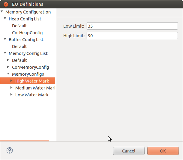 3. Click on each Water Mark and enter the following information:
- Low Limit: Memory limit value for downward crossing in bytes.
- High Limit: Memory limit value for upward crossing in bytes.
4. Double-click each Water Mark to specify one or all of the following actions:
- Event
- Log
- Custom
5. Click Event and select true or false from the drop-down list. If it is set to true , event is enabled. Similarly, you can enable Log and Custom actions. 6. Click OK to save the memory profile.
9.2 Assigning Memory Configuration Profiles to Components
After you have completed creating the memory configuration profiles, you can assign them to the various ASP components and the user-defined EOs in the EO Configuration window. By default, the Default memory configuration profile is associated to the components.
To assign the memory configuration profile to the SAFPluse components or user defined components:
1. From the Clovis menu, click EO Configuration or click the icon on the toolbar. The EO Configuration window is displayed.
2. Click SAFPluse Components to assign memory configuration profiles to 'SAFPluse components. The 'SAFPluse component list is displayed.
or
Click User Defined EOs to assign memory configuration profiles to user defined components.
3. Select the component to which you need to assign the memory profile.
4. Click Edit for EO Memory Config. The EOMemConfig Details window is displayed.
5. Select the default or user-defined memory configuration profiles for Heap, Buffer, and Memory.
6. Click OK to save and close EOMemConfig Details window.
7. Click OK to close the EO Configurations window.
CHAPTER 10
'Creating and Using Template Groups
This chapter provides information about creating and using the template groups to generate the source code. The source code is built using the default templates that is in C language. You can also create source codes in C++ language.
Key Topics:
- Creating Template Group
- Using Template Groups
- Modifying Template Groups
10.1 Creating Template Group
The template groups are created using the Manage Template Group(s) window. You can also use the default template. After creating the template group, it appears in the Clovis Workspace pane.
1. From the Clovis menu, click Manage Template Groups or click the icon from the toolbar to open the Manage Template Group(s) window.
2. Click Add to add a new template group. The window is displayed.
3. Enter a name for the template group and click OK. The name is displayed in the Manage Template Group(s) window and it is available under the templates folder in the Clovis Workspace Pane.
Click Rename to rename the selected template group.
Click Remove to remove the selected template group.
10.2 Using Template Groups
After you have completed creating the template group, you can assign it to the various SA Forum components in the Component Editor. By default, the default template group is associated to the components. You can also associate the user defined template group.
To assign the template group to the SA Forum component:
1. From the Clovis menu, click Associate Template Group or click the icon on the toolbar. The Associate Template Group window displays all the SA Forum components in the Component Editor to which you can assign the template group.
2. Select the template group from the list and click OK. The template group is assigned to the SA Forum component.
10.3 Modifying Template Groups
After creating template groups, you can customize the template groups per model as well as per application. All the templates will be availabe under templates folder. If you want to use the modified template files for entire model, modify the template files which are under templates/default. If you want to use the modified template files for any one of the application, modify the template files which are under templates/<TemplateGroupName>.
templates folder contains two type of templates:
- python template files
- .c and .h files.
Most of the python template files have two type of template static and runtime. static python templates are simply copied in some of the .c or .h files through python script at the time of code generation. static python templates are looks like:
headerTemplate = Template("""\ ClRcT clProvRead(CL_OM_PROV_CLASS* pThis, ClHandleT txnHandle, ClProvTxnDataT* pProvTxnData) { ClRcT rc = CL_OK; return rc; } """)
runtime python templates are copied in some of the .c or .h files with some modifications through python script. Modifications will happen based on some xml entries. runtime python templates are looks like:
headerTemplate = Template("""\ ClRcT cl${compName}${res}ProvRead(CL_OM_PROV_CLASS* pThis, ClHandleT txnHandle, ClProvTxnDataT* pProvTxnData) { ClRcT rc = CL_OK; return rc; } """)
Values for compName and res will be substituted through python script at the time of code generation.
All the .c and .h files will be copied to app/<CompName> folder at the time of code generation.
10.3.1 Adding Application Code Blocks
If you want to use same TemplateGroup for multiple applications and also you want to write some apllication code in generated source files, identify the blocks in template(s) which you will modify after generating the source. Insert this tag in each blocks,
# ---BEGIN_APPLICATION_CODE---
# ---END_APPLICATION_CODE--
or
/* ---BEGIN_APPLICATION_CODE--- */
/* ---END_APPLICATION_CODE--- */
This code blocks will be used to identify the user code. After generating source you can use this blocks to add your application code. Next time when you generate source all the code with in the blocks will be moved in to newly generated code.
CHAPTER 11
Defining IDL
This chapter provides information about creating the IDL XML file that is used to generate marshalling and unmarshalling code for communication between two or more components.
The OpenClovis Interface Definition Language (IDL) is a library used by all components to communicate efficiently with other components. Using IDL, OpenClovis ASP services can communicates across different endian and mixed mode (32-bit and 64-bit architecture) machines.
IDL generated code is a wrapper over RMD and supports RMD functionality to provide communication across components. RMD consists of an engine which provides the ability to invoke methods from one component to another component. By defining an IDL, the XML file is created which is read by the Python script and the C code is generated. The created XML file is located in your workspace and the generated C code is located in the <projectarea_directory>/<model_name>/src/app/idl folder. You can customize this XML file for your specific requirements.
Each component may define a set of operations associated with it. The RMD calls are defined through the functions defined in the component. The component from where the call or request is invoked is called the source and the component that receives the request is called the destination. When a remote call is invoked, the RMD sends a message to the destination using the underlying IOC transport layer. The component that receives the request invokes the function that is being requested.
Components can expose different types of services. Services of one component are grouped under service group. Each service has a operation group that logically separates the functions of a service. Hence, to define an IDL, you have to create the service group list that consists of services, operation groups, and the associated arguments. You can also create the data types required for the arguments such as structures, unions, and enumerations.
Key Topics:
- Defining Service Group List
- Creating User Defined Data Types
11.1 Defining Service Group List
A Service Group List comprises the following:
- Service Groups
- Services
- Operation Groups
- Operations
To define the Service Groups:
1. From the Clovis menu, select Remote Method Definitions or press Shift+Ctrl+I on the keyboard. The RMD window is displayed. In this window, you can specify the services for each component.
2. Right-click Service Group List and select New to create a new service group. Select the service group from the drop-down list.
This list displays the list of service group provided for all the components.
3. Double-click the newly created service group to display the Service List.Right-click and select New.
Enter the following information:
- Service Name: This is the name of the service in which the operations of the service resides. Enter a valid C identifier.
- Use Native Table: If a component is providing service to other component(s), the native (default) table is used. Select true or false from the drop-down list. If you set this to true , the default table is used. If it is set to false , another table is generated automatically by IDL. This is typically used when the response message is sent by invoking an operation on a caller.
4. Double-click the created service to display the Operation Group List. Right-click and select New to create a new operation group.
Enter the following information:
- Operation Group Name: This is the name for the operation group that consists of the functions. You can define more than one operation group to logically separate the functions for a service. Enter a valid C identifier.
5. Double-click the created operation group to display the Operation List.Right-click and select New to specify the operations or functions.
Enter the following information:
- Operation Name: Name for the operation or function associated with the component to which RMD calls can be made. Enter a valid C identifier.
- Arguments: Click Edit to enter the argument details for the operation. Argument is similar to a data member. Argument details consists of the input or output parameters associated with this operation. The Argument Details window is displayed. Click New to create a new argument.
Enter the following information:
- Parameter Type: Type of the parameter for the argument. Select the parameter type from the list. The options available are:
- CL_IN: This argument parameter is an input to the operation.
- CL_OUT: This argument parameter is used to return the value back to the caller.
- CL_INOUT: This argument parameter is an input to the operation and is also used to return the value back to the caller.
- Name: Name of the argument. Enter a valid C identifier.
- Data Type: Data type for the argument. Select the data type from the list.
The pre-defined data types available are:
- ClInt8T
- ClUint8T
- ClInt16T
- ClUint16T
- ClInt32T
- ClUint32T
- ClInt64T
- ClUint64T
- ClCharT
![]() You can also have user defined data types like Structures, Unions, or Enumerations. For information about creating user-defined data types, see Creating User Defined Data Types section. After you create the user-defined data type, they will appear in this drop-down list.
You can also have user defined data types like Structures, Unions, or Enumerations. For information about creating user-defined data types, see Creating User Defined Data Types section. After you create the user-defined data type, they will appear in this drop-down list.
- Pointer: If the argument is of pointer type, select the level of indirection. The available options are:
- None
- Single
- Double
![]() All CL_OUT type of argument must be either single or double pointer. CL_IN or CL_INOUT argument type cannot be a double pointer.
All CL_OUT type of argument must be either single or double pointer. CL_IN or CL_INOUT argument type cannot be a double pointer.
- Length Variable: If the argument is of the pointer type, select another argument that contains the length of the data pointed by this argument. The default value is None. If you create other arguments, they appear in this list.
![]() You can specify the Length Variable when the argument type is a single pointer or when the argument type is CL_OUT and is a double pointer. If the argument is of the pointer type and length variable is None , the length of the data pointed is of the defined data type within the argument.
You can specify the Length Variable when the argument type is a single pointer or when the argument type is CL_OUT and is a double pointer. If the argument is of the pointer type and length variable is None , the length of the data pointed is of the defined data type within the argument.
6. Click OK. The Arguments Details window closes.
7. Click OK. The IDL is saved and the XML file is located in the idl folder in your workspace.
11.2 Creating User Defined Data Types
IDL uses XDR representation to Marshall application data while transferring it to another component. Therefore, IDL requires the application to specify the data structures to be transferred through RMD, so that it can generate XDR functions required to marshal/un-marshal these data structures. Marshaling is the process of converting the native data to XDR format and un-marshaling is retrieving the data back to native format. You can define the following user-defined types for each component:
- Structures
- Unions
- Enumerations
11.2.1 Defining Structures
Structures are similar to structures in C. Therefore, every defined structure is composed of data members. You can define two structures separately and embed one inside another as a data member.
You can define structures in the RMD window. Right-click on the Struct List tand select New. STRUCT0 is created by default under Struct List.
Enter the following information:
- Name: This is the user-defined structure name. Enter a valid C identifier. When you rename the structure, the new name replaces the default name on the left pane.
- Struct Member: Click Edit to specify the data member details. The Data Member Details window is displayed. Click New to enter a new data member.
Enter the following information:
1.Name: :Name of the data member of the structure. Enter a valid C identifier.
2.Data Type: Data type of the structure member. This can be a pre-defined data type or a user-defined type. Select the data type from the drop-down list. It is the your responsibility to ensure that there are no circular inclusions. Circular inclusions occur when two or more user-defined data types include each other in their respective definitions in such a way that it creates a cyclic dependency among st the involved user-defined data types.
3.Pointer: Select the value from combo-box to specify whether the structure member is a pointer or not. When Single is selected, it means that the data member is a pointer to the specified data type. The options available are:
- None
- Single
4.Length Variable: If the structure member is not a pointer, select None. Otherwise, select the name of the other member in this structure that contains the length of the data pointed by this member. This attribute should be specified only if the pointer type is set to Single. This attribute specifies which data member in the structure will contain the number of elements being pointed to. When none is specified for a pointer type data member, it is assumed that a single element is being pointed to.
5.Multiplicity: Defines the number of elements in the array. Used only if the attribute is an array. This attribute must not be specified along with the pointer attribute.
Click OK. The data member details are saved and the Data Member Details window closes.
- Generate Definition: Select this option to specify the definition for the user-defined data type. If you select true, Include Header File Path option is disabled and definition will be generated during code generation. If set to false, you must provide the path for the .h file that has the definition.
- Include Header File Path: Click Edit to include the path. Specify the path for appropriate .h file and click OK. If you select Generate Definition as false, then you must provide the path.
Click OK. The structure is created.
11.2.2 Defining Union
These are defined similar to structures. The difference is in terms of the interpretation and generation.
You can define unions in the RMD window. Right-click on the Union List and select New to create a new union. UNION0 is created by default under Union'List'.
Enter the following information:
- Name: This is the union name. Enter a valid C identifier. When you rename the union, the new name replaces the default name on the left pane.
- Union Member: Click Edit to specify the data member details. The Data Member Details window is displayed.
Enter the following information:
- Name: :Name of the data member of the union. Enter a valid C identifier.
- Data Type: Data type of the union member. This can be a pre-defined data type or a user-defined type. Select the data type from the drop-down list. It is the your responsibility to ensure that there are no circular inclusions. Circular inclusions occur when two or more user-defined data types include each other in their respective definitions in such a way that it creates a cyclic dependency among est the involved user-defined data types.
- Pointer: Select the value from combo-box to specify whether the union member is a pointer or not. When Single is selected, it means that the data member is a pointer to the specified data type. The options available are:
- None
- Single
- Length Variable: If the union member is not a pointer, select None. Otherwise, select the name of the other member in this union that contains the length of the data pointed by this member. This attribute should be specified only if the pointer type is set to Single. This attribute specifies which data member in the union will contain the number of elements being pointed to. When none is specified for a pointer type data member, it is assumed that a single element is being pointed to.
- Multiplicity: Defines the number of elements in the array. Used only if the attribute is an array. This attribute must not be specified along with the pointer attribute.
Click OK. The data member details are saved and the Data Member Details window closes.
- Generate Definition: Select this option to specify the definition for the user defined data type. If you select true, Include Header File Path option is disabled and definition will be generated during code generation. If set to false, you must provide the path for the .h file that has the definition.
- Include Header File Path: Click Edit to include the path. Specify the path for appropriate .h file and click OK. If you select Generate Definition as false, then you must provide the path.
Click OK. The union is created.
11.2.3 Defining Enumeration
Enumerations are similar to enums in C. You can define enumerations in the RMD window. Right-click on the Enum List and select New to create a new enum. ENUM0 is created by default under Enum List.
Enter the following information:
- Name:This is the enumeration name. Enter a valid C identifier.
- Enum Member:Click Edit. TheEnum Member Detailswindow is displayed. Click New to create new enumeration data member.
Enter the following:
1.Name: Name of the data member of the enum. Enter a valid C identifier.
2.Value: Value for the data member. Click OK. The data member details are saved and the Enum Member Details window closes.
- Generate Definition: Select this option to specify the definition for the user defined data type. If you select true, Include Header File Path option is disabled and definition will be generated during code generation. If set to false, you must provide the path for the .h file that has the definition.
- Include Header File Path: Click Edit to include the path. Specify the path for the appropriate .h file and click OK. If you select Generate Definition as false, then you must provide the path.
Click OK. The enumeration is created.
CHAPTER 12
Generating Source Code
This chapter provides information about generating the source code after you have completed building the model.
To generate the code, in the OpenClovis IDE window, from the Project menu, click Generate Source. On successful generation of the source code, a message is printed on the Console pane at the bottom of the OpenClovis IDE window.
The generated source code is located at <projectarea_directory>/<model_name>/src directory. The projectarea_directory is specified in the Clovis System Project window.
As source code is generated it is copied, along with various configuration files from the IDE model to the ASP model. Although not recommended, you may have made some manual changes to these ASP configuration files. You may also have made changes to generated source code outside of the prescribed begin/end application code blocks. The process of generating code will overwrite these changes. The IDE provides you an opportunity to backup these files before they are overwritten during code generation. Depending on your project settings you may see the following dialog.
- Yes: Backs up the existing source and configuration files into the directory specified and then proceeds with code generation.
- No: Proceeds with code generation without backing up the source and configuration files.
- Cancel: Stops code generation without making any changes.
- Never show this dialog again: Selecting this check-box will persist the selection made with the Yes or No buttons as a project property and always use this option when generating source code.
![]() Only one backup version of a project’s directory directory is maintained.
Only one backup version of a project’s directory directory is maintained.
![]() If you have selected Never show this dialog again but want to now change the backup mode you can do this through the Project Property dialog. See the section Setting Project Properties.
If you have selected Never show this dialog again but want to now change the backup mode you can do this through the Project Property dialog. See the section Setting Project Properties.
12.1 Merging User Application Code
When you generate the code for the model which already has the user code, IDE will find the diff for generated code with existing user code and display the list of modified files in the Merge window.
- Merge: Select files in the list and click Merge button. All user code placed within the following blocks will be moved into the newly generated code.
---BEGIN_APPLICATION_CODE---
---END_APPLICATION_CODE---
- Override: Select files in the list and click Override button. all user code will be overridden by generated code.
- Override All: This will override all the user code.
- Always wants to override application code: Select this option if you want to override application code every time.
- Always wants to merge application code: Select this option if you want to merge application code every time.
12.2 SNMP auto code genaration
If you have SNMP sub-agent in your model and you want to use SNMP auto code generation, before generating source code you need to enter MIB directories location and module name in SNMP Properties Dialog for SNMP sub-agent component. For more information, see Setting SNMP sub-agent Properties section in Chapter 7, Setting Component Properties.
CHAPTER 13
Building the Project
Building the project takes the generated source code files and uses them to build the project executable file. This executable is located in the target folder in the
'<projectarea_directory>/<model_name>/src directory. To build the project select the Project > Build Project menu item. The Build Configuration dialog appears.
Enter the following information:
- Use pre build SAFPlus: Select this checkbox to use prebuilt ASP libraries. When checked the field to the right will become enabled. This field holds the location of the pre build SAFPlus libraries. To get more information about pre-building ASP libraries, see OpenClovis SDK User Guide .
- With cross build: Select this check box to build the code for another CPU. Also select the CPU from the drop-down list.
![]() This option is only available if you have installed cross-build tool chains during the installation process.
This option is only available if you have installed cross-build tool chains during the installation process.
- With Kernel build: Select this check box to build the code for another Kernel version. Also, specify the CPU in the text box.
- Include SNMP for North Bound Access: Select this checkbox to include SNMP libraries. If you do not include SNMP build, it does not build the SNMP server in ASP and the SNMP agent in the model. If your model has SNMP dependencies, then this should be turned on to compile and link with the installed SNMP utilities.
- Include Chassis Manager for HPI Access: Select this checkbox to include Chassis Manager (CM) component. This is used to build ASP for an ATCA environment where there is a Shelf Manager that communicates through the Hardware Platform Interface (HPI).
Select an option from the drop-down menu. The options available are radisys and openhpi.
![]() The Include Chassis Manager for HPI Access checkbox is only enabled if a Platform Support Package is installed within the project’s configured SDK location.
The Include Chassis Manager for HPI Access checkbox is only enabled if a Platform Support Package is installed within the project’s configured SDK location.
- Force Configure: Select this check box to forcefully configure the project before build.
Click OK to build the project.
When complete a build output message is printed on the Console pane at the bottom of the OpenClovis IDE window.
![]() Project building and image generation (explained in the following section) can also be accomplished from the Linux command line. For more information on the command line based process, see the respective sections of the OpenClovis SDK User Guide : Building ASP and ASP-based Systems and Deploying and Running OpenClovis ASP on a Target System.
Project building and image generation (explained in the following section) can also be accomplished from the Linux command line. For more information on the command line based process, see the respective sections of the OpenClovis SDK User Guide : Building ASP and ASP-based Systems and Deploying and Running OpenClovis ASP on a Target System.
CHAPTER 14
Making Project Images
Making project images takes the project executable that was created during build project and packages it for deployment in a specific environment. To make the project images select the Project > Make Images menu item. The Make Images Configuration dialog appears with three tabs.
General tab is used to indicate information about the environment on which the images will be deployed. This information is used to tailor the images to run on that environment.
- Create Node Specific Images: This check box indicates whether to create node specific images or single image for all nodes.
- Package Images into Tarballs: This check box indicates whether to package the images into tarballs.
- Node Instance Information: This table contains a row for each node instance that was defined in the model. The values in the rows are used to specify how the node instance will be deployed on the ASP cluster.
1.Node Instance: This read-only field displays the name of the node instance.
2.Slot Number: This value represents the slot in the chassis on which the node instance will run. This field is a drop down list of slot numbers. The values in this list are determined by the ’Number of slots’ field in the Chassis Resource Details dialog in the Resource Editor.
3.Network Interface: This value indicates the port on the target blade that the node instance will use to communicate to other blades in the chassis.
Chassis Management tab is used to indicate how the nodes in the ASP cluster will communicate with the chassis management module if the project has been set to include chassis management for HPI access during the build process.
![]() These fields will be disabled if the project is not configured to include chassis management.
These fields will be disabled if the project is not configured to include chassis management.
- Module IP: This value is the IP address of the target chassis management module. Required if the project is configured to include chassis management.
- Authentication Type: This value indicates the method of authentication that will be used when logging into the chassis management module. This field contains a drop-down list of values.
- Username: This value represents the user name of the acount that will be used when logging into the chassis management module.
- Password:This value represents the password of the acount that will be used when logging into the chassis management module.
3rdParty tab is used to add bin and lib files for the 3rd party components. These added files will be included in final images.
![]() These controls be only enabled if a component in the model has been configured as a 3rd party component.
These controls be only enabled if a component in the model has been configured as a 3rd party component.
- Add Bins...: This control is used to add 3rd party component’s binary files.
- Delete Bins: This control is used remove the binary files from existing List.
- Add Libs...: This control is used to add 3rd party component’s library files.
- Delete Libs: This control is used remove the library files from existing List.
TIPC Specific: Inter process communication
- Trap IP: This value specifies where the SNMP sub-agent will send traps at runtime. This field is optional but if specified must be a valid IP address.
- TIPC Net ID: This value represents a unique identifier used by TIPC to set up interprocess communication across the deployed OpenClovis ASP cluster. This is an unsigned 32-bit integer, and should be unique for every model that is deployed. This will allow multiple models/clusters to run within the same network LAN without interference.
UDP Specific: This Provides Transport Layer Facility
![]() Image generation can also be accomplished from the Linux command line. For more information on the command line based process, see the section Deploying and Running OpenClovis ASP on a Target System in OpenClovis SDK User Guide
Image generation can also be accomplished from the Linux command line. For more information on the command line based process, see the section Deploying and Running OpenClovis ASP on a Target System in OpenClovis SDK User Guide
Deploy Project Images
Deploy Project Images takes the tarred and non-tarred images and deploy in to the target machines. To deploy the images select the Project > Deploy Images menu item. The Deploy Images dialog appears.
Enter the following information for each node:
- Target address: IP address of target machine.
- User name: User name for the target machine.
- Password: Password for the corresponding User name.
- Target location: Directory location to deploy the image.
Click Deploy to deploy the images.
When complete a deploy output message is printed on the Console pane at the bottom of the OpenClovis IDE window.
![]() To deploy all the available images click Deploy All.
To deploy all the available images click Deploy All.
![]() Deploy Image can also be accomplished from the Linux command line. For more information on the command line based process, see the section Deploying and Running OpenClovis ASP on a Target System in OpenClovis SDK User Guide .
Deploy Image can also be accomplished from the Linux command line. For more information on the command line based process, see the section Deploying and Running OpenClovis ASP on a Target System in OpenClovis SDK User Guide .
CHAPTER 15
XML Representation of the Model
The OpenClovis IDE helps you to build the Clovis Information Model (IM) and subsequently generate code and configuration files. The information required by the IDE is stored in well-defined XML files which conform to a published schema. This document describes the organization and content of these XML files which are part of the OpenClovis project that can be read by the IDE. This document along with the XML schemas should provide you with the insight into creating a project and populating the corresponding XML files.
Key Topics :
- Overview
- File Organization
- File Specification
![]() This document does not describe the individual XML attributes/elements that go into the files. For information about the configurable fields, refer to the relevant chapters within this guide.
This document does not describe the individual XML attributes/elements that go into the files. For information about the configurable fields, refer to the relevant chapters within this guide.
15.1 Overview
The Model for an IDE project is stored in XML files in an open and well-defined format. The OpenClovis IDE is able to import any project model that conforms to the schema and organization of the project files as described in this chapter. These files can be generated by you using any tool of your choice and you can subsequently import and manipulate the project through the IDE.
![]() It is your responsibility to ensure that the information contained in the files is consistent and valid. There should not be any incorrect references or erroneous information in the files as this will lead to incorrect behavior of the IDE as well as failure to import the model.
It is your responsibility to ensure that the information contained in the files is consistent and valid. There should not be any incorrect references or erroneous information in the files as this will lead to incorrect behavior of the IDE as well as failure to import the model.
The schema for all the project XML files is also provided in .xsd form with comments to help you in creating the XML files.
![]() If you need to store your project in the version control system (example, SCM), the complete project workspace directory has to be stored. The relevant project XML files are explained in the later part of this chapter.
If you need to store your project in the version control system (example, SCM), the complete project workspace directory has to be stored. The relevant project XML files are explained in the later part of this chapter.
15.2 File Organization
The organization of the set of project files for each individual project must be as shown in Figure Directory Organization.
![]() If you have used another tool to create the project, you need to import your project into OpenClovis IDE.
If you have used another tool to create the project, you need to import your project into OpenClovis IDE.
The information is provided in different files in different directories as illustrated in Figure Directory Organization.
Directory: <Project root>
FileName: .project
This is a mandatory file for each project and must be present.
A sample .project file is as shown in Figure Sample .project File.
Directory: models
- Resource Configuration
- Component Configuration
- Alarm Configuration
- Component Resource
- Association Resource
- Alarm Association
Directory: configs
- AMF Instance Configuration
- ASP Component Configuration
- Node Admission Control Configuration
- IOC Configuration
- GMS Configuration
- EO Profile Definition
- EO Configuration
- Node Instance Configuration
Directory: idl
- RMD Configuration
Others: The following files and directories are typically updated when the project (after import) is updated through the IDE. You do not have to populate these files.
- scripts
- templates
- config.xml, config.sh, build.xml, build.sh
15.3 File Specification
This section provides information about each XML file that is part of the project and describes its role in the model.
![]() The model requires configuring an unique rdn string for the entities defined in alarm, resource and component configuration files.
The model requires configuring an unique rdn string for the entities defined in alarm, resource and component configuration files.
The sample XML files are provided for the following:
- Resource Configuration
- Component Configuration
- Model Map Information
- AMF Instance Configuration
- RMD Configuration
- ASP Component Configuration
- Node Admission Control Configuration
- GMS Configuration
- Log Service Configuration
- Node Instance Configuration
- EO Profile Definition
- EO Profile Configuration
![]() The sample XML files provided as illustrations in this section do not reflect the exact contents of the files. Only relevant parts of the XML files are provided here.
The sample XML files provided as illustrations in this section do not reflect the exact contents of the files. Only relevant parts of the XML files are provided here.
15.3.1 Resource Configuration
File Name: resourcedata.xml
This file specifies the resource information. This primarily consists of a single Chassis type resource along with three types of resources:
- Node Hardware Resource (typically represents a blade type)
- Hardware Resource
- Software Resource For each of the resource classes, you can specify:
- Private Attributes
- Provisioning Attributes
- Alarms In addition to the Node Hardware Resource and Hardware Resource classes, you can specify and associate device objects.These classes are connected by containment (composition) and inheritance relationships.
A sample resourcedata.xml file is shown in the following illustration.
15.3.2 Component Configuration
File Name: componentdata.xml
This file contains information about all the component classes and their mutual relationships:
- Node
- Service Unit
- Component
In case of SAF component - it additionally contains EO information
- Service Group
- Service Instance
- Component Service Instance For each of the entities, you can specify the values of the attributes.
A sample componentdata.xml file is shown in the illustration.
15.3.4 Model Map Information
The model map file contains information that provides a mapping association between entities defined in two different model files. Currently, there are two categories of model map files.
15.3.4.1 Component Resource Association
File Name: component_resource_map.xml
This file provides information about the association between SAF component and resource classes. For each SAF component, you can specify the list of resources that are associated with it. The SAF component and resource classes have to be defined in the component data and resource data files.
A sample component_resource_map.xml file is shown in the following illustration.
15.3.4.2 Resource Alarm Association
File Name: resource_alarm_map.xml
This file provides information about the association of alarms with resource classes. For each resource class, you can specify the set of alarms associated with the resource. Also for each associated alarm, you can define the generation and suppression rule. The alarm and resource classes have to be defined in the component data and resource data files.
A sample resource_alarm_map.xml file is shown in the following illustration.
15.3.5 AMF Instance Configuration
File Name: clAmfConfig.xml
This file contains information about AMF instances in the deployment. The complete deployment configuration in terms of the node instances, SU instances, and component instances is specified along with the information about SG, SI, and CSI instances.
A sample clAmfConfig.xml file is shown in the following illustration.
15.3.6 RMD Configuration
File Name: server_idl_interface.xml
This file contains information about all the services to be provided by all the EOs in the system. For each of the EO, you can provide information about the corresponding ports, groups, services, and the expected arguments for the ports. If any of the arguments is user-defined, they must also be specified in this file.
A sample server_idl_interface.xml file is shown in the following illustration.
15.3.7 ASP Component Configuration
File Name: compileconfigs.xml
This file contains various configuration parameters for ASP components like COR, IOC, and so on.
A sample compileconfigs.xml file is shown in the following illustration.
15.3.8 Node Admission Control Configuration
File Name: clSlotInfo.xml
This file contains information to be used in Node Admission Control. For each slot, you should provide a list of Node Type classes that should be allowed in that slot. The Node Type classes should match those configured in the componentdata.xml file. Also, the number of slots should match the number of slots provided for the Chassis resource in the resourcedata.xml file.
A sample clSlotInfo.xml file is shown in the following illustration.
15.3.9 GMS Configuration
FileName: clGmsConfig.xml
This file contains information to be consumed by the Group Membership Service.
A sample clGmsConfig.xml file is shown in the following illustration.
15.3.10 Log Service Configuration
FileName: clLog.xml
This file contains the configuration of the common log service parameters, and the config parameters of the perennial and pre-created log streams.
A sample clLog.xml file is shown in the following illustration.
15.3.11 Node Instance Configuration
File names(s): Node Instance Name_rt.xml
For each node instance configured in the clAmfConfig.xml file, there must be a file of the form <Node Instance Name>_rt.xml . This file contains information about the following:
- The component instances that will be running on that node instance.
- For each component instances, the MOIDs of the resource instances that they are managing.
A sample GigeNode0_rt.xml file is shown in the following illustration.
15.3.12 EO Profile Definition
FileName: clEoDefinitions.xml
This file contains various memory profiles that can be defined by the user. This include:
- Heap Configuration
- Buffer Configuration
- Memory Configuration
A sample clEoDefinitions.xml file is shown in the following illustration.
15.3.13 EO Profile Configuration
FileName: clEoConfig.xml
This file contains the information which applies specific memory configurations to each Execution Object for all the SA Forum Components defined in the componentdata.xml file. Additionally, it contains memory configurations for all the ASP components.
A sample clEoConfig.xml file is shown in the following illustration.
CHAPTER 16
Creating and Building openSAF Project in IDE
This chapter provides information about how to create and build the openSAF project.
16.1 Creating openSAF Project
Creating openSAF model is similar like creating OpenClovis project except Code generation mode option in the Project Properties page. By default IDE maintains Code generation mode option as openclovis. So to change this option, in the OpenClovis IDE window, from the Project menu, click Properties and change Code generation mode value to openSAF.
16.2 Generating Source for openSAF Project
This chapter provides information about generating the source code after you have created openSAF project.
To generate the code, in the OpenClovis IDE window, from the Project menu, click Generate Source. On successful generation, the source code tree looks like this,
The generated source code is located at <projectarea_directory>/<model_name>/src/openSAF directory. The projectarea_directory is specified in the Clovis System Project window.
16.3 Building openSAF Project
To build the project select the Project > Build Project menu item. When complete a build output message is printed on the Console pane at the bottom of the OpenClovis IDE window.
After building you can find the image opensaf_app_bundle.tgz inside <projectarea_directory>/<model_name>/src/openSAF directory.
CHAPTER 17
Model Templates
This chapter provides information about Model Templates feature provided by OpenClovis IDE. You can select resources from the Resource Editor / components from the Component Editor and save them as custom templates. These templates appear in the Model Template tab. These templates can be reused for creating resource tree in the Resource Editor / component tree in the Component Editor for other projects in the same workspace.
Key Topics:
- Creating Model Template
- Using Model Template
- Importing Model Template
- Exporting Model Template
- Refreshing Model Template View
17.1 Creating Model Template
User can create model template for entities in Resource editor as well as Component Editor. Model template created with the entities in Resource Editor is referred to as Resource Model Template. While Model Template created with the entities in Component Editor is referred to as Component Model Template or Application. How to create both the types of model templates is explained below.
17.1.1 Resource Model Template
To create a Resource Model Template:
1. In the Resource Editor, right-click on a resource and select Create Model Template.... The Model Template Details dialog box is displayed.
2. Enter the following information:
- Name: This is the name of the model template which is by default selected as corresponding resource name.
- Include Child Hierarchy: Select true or false. If you select true, all the child resources for the selected resource are also included as part of the template.
- Include Related Entities : Select true or false. If you select true, the alarms associated with the selected resource are saved as part of the template.
3. Click OK. The Model Template Details dialog box closes and the created template appears in the Model Template view under the Resource Template tab.
17.1.2 Component Model Template (Application Template)
To create a Component Model Template:
1. In the Component Editor, ctrl+click entities which are made to be part of the template. Now right-click on any of the selected entities and select Create Model Template.... The Model Template Details dialog box is displayed.
2. Enter the following information:
- Name: This is the name of the model template which is by default selected as one of the selected entities’ name.
- Include Source: Select true or false. If you select true, source code for that component/application is also included as part of the template.
- Include Related Entities : Select true or false. If you select true, the resources associated with the selected components and the alarms associated with those resources are saved as part of the template.
3. Click OK. The Model Template Details dialog box closes and the created template appears in the Model Template view under the Component Template tab.
17.2 Using Model Template
You can use the saved model templates inside another model. To use the model template:
1. In the Model Template view, expand Resource Template or Component Template tab and select the template that you need to use. The selected template is displayed under Selected Template.
2. User can see the complete structural details for the model template under the Selected Template. This shows components, resources and alarms which are part of the model template, their internal structure and mapping information for them.
3. Click Uses the Model Template icon inside tool bar at the top right corner of the Model Template view. All the components, resources and alarms which are part of the model template are copied into the model of the currently selected project along with their mappings. Entities for the selected model template are displayed in the Resource Editor or Component Editor depending on the type of the template. If any of the entities of model template is already present in the model then validation will capture this and corresponding message is displayed to user.
17.3 Importing Model Template
To import a Model Template:
1. In the Model Template tab, click Imports the Model Template icon. The Model Template Import Dialog box is displayed.
2. Click Browse and specify the directory from which you need to import. The location of the files is displayed in From Directory and all the available model template file(s) under that directory are displayed in the box.
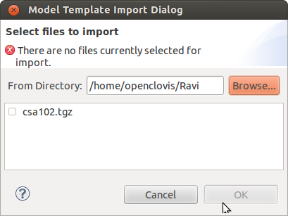
3. Select the files that you want to import. 4. Click OK. The selected file(s) are imported.
17.4 Exporting Model Template
To export a Model Template:
1. In the Model Template tab, click Exports the Model Template icon. The Model Template Export Dialog box displays all the templates that are part of the model.
2. Select the file(s) that you need to export. Click Browse and specify directory to where you need to export the file(s). The location of the file(s) is displayed in To Directory.
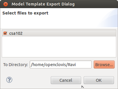
3. Click OK. The file(s) are exported to the specified location
17.5 Refreshing Model Template View
To refresh the Model Template view, click the Refreshes the Model Template View icon at the top-right corner of the Model Template tab. This synchronizes the model template view with file system.
CHAPTER 18
Application Import/Export
This chapter provides information about Application Import/Export feature provided by OpenClovis IDE. Please refer Importing Model Template and Exporting Model Template in the previous chapter on Model Template to get the detailed information for this feature.
Here we will discuss express import application support available for the user who wants to use the application provided by OpenClovis or created by themselves directly into the IDE model. This is a functional combo of Importing model template and using it into the IDE model.
To express import an application:
1. Select Import Applications... option from top level clovis menu or from the tool bar. The Import Application Dialog box is displayed.
2. Click Browse and specify the directory from which you need to import. The location of the files is displayed in From Directory and all the available application file(s) under that directory are displayed in the box.
3. Select the files that you want to import.
4. Click OK. The selected file(s) are imported. All the components, resources and alarms which are part of the application are copied into the model of the currently selected project along with their mappings. Entities for the selected model template are displayed in the Component Editor. If any of the entities of application is already present in the model then validation will capture this and corresponding message is displayed to user.
CHAPTER 19
Limitations
19.1 X Error in Ubuntu Installation
If you start the IDE in Ubuntu installation you may see some X errors in the con-sole like,
X Error: BadDevice, invalid or unitialized input device 169
Major opcode: 145
Minor opcode: 3
Resource id: 0x0
Failed to open device
This is not an IDE issue also this will not affect any of the IDE functionalities. To avoid this error messages just follow this http://kubuntuforums.net/forums/index.php?topic=7964.0
CHAPTER 20
Glossary of Terms
Alarm An alarm is a warning about the abnormal conditions of Managed Object (MO).
![]() An alarm always does not represent an error.
An alarm always does not represent an error.
Alarm Lifecycle The Alarm Managed Service Object (MSO) associated with an MO depicts the lifecycle of an alarm as:
- An alarm is raised by the alarm service, if the abnormal condition relating to the alarm persists for a time, at least equal to the soaking interval specified. This alarm may be cleared by:
1.The alarm service, when it gets a notification from the MO that the abnormal condition which caused the alarm has been cleared.
2.An explicit command from an operator using the management interface.
3.RESET, if the MO is hardware, and RESTART, if the MO is software Execution Object (EO).
Alarm Manager The alarm manager enables configuring and handling of alarms. It provides support for alarm soaking, masking, alarm hierarchies, retrieving previous alarm conditions, and correlation of the alarms before publishing.
Alarm Masking Multiple alarms can be raised in a system. Alarm-masking is a procedure that enables the alarm service to publish the alarms with high priority for fault recovery.The current alarm-masking logic implies that all MOs are organized in a fault containment hierarchy which represents the relationship "is physically contained in" for hardware and "runs on" for software. The alarm-masking algorithm masks all alarms of the same or lesser severity level within any sub-tree in the hierarchy.
Alarm Service The OpenClovis alarm service implements a generic engine to process abnormal conditions reported by managed resources. The process includes identifying the alarm type and its severity level and determining whether an alarm has to be raised after running it through soaking and masking procedures.Potential subscribers for alarm events are - OpenClovis Fault Management Service, OpenClovis Availability Management Service and other agents like SNMP, CLI, and so on for reporting alarms to external managers.
Alarm Severity The alarm severity specifies the condition of the service provided by the MO. The severity levels can be critical, major, minor, warning, or cleared and indeterminate (CCITT X.733). The cleared and indeterminate level indicates clearing of one or more previously reported alarms. The critical and major alarms are service-affecting alarms.
Alarm Soaking Soaking is the time defined for extreme conditions before reporting as an alarm. Alarm soaking is possible when a managed resource provides a pair of notifications - one for the occurrence of an extreme condition and another for clearing of the extreme condition. Soaking avoids raising an alarm unless the extreme condition of the alarm persists for a period of time. Sometimes, you may not get a notification for clearing of an extreme condition. In such cases, a poll mechanism can be used to see if the alarm condition is still present after the soaking interval.
Application An Application is customer software built using OpenClovis infrastructure that provides services to the end users. For instance: A SIP server customer application.
ASP Console A command-line Interface for debugging allows access to the managed object repository for creating, deleting and otherwise manipulating objects. ASP Console also provides viewers for system log and trace data as well as interfaces to individual EOs to view and modify their private (non-persistent) data.
Attributes Attributes are the characteristics or parameters of a Managed Object.
Availability Management Framework (AMF) AMF is a software entity that provides a framework for high availability of applications in a system. It is responsible for instantiating and managing all the OpenClovis ASP services. It executes configured recovery actions on the failure of application components. The AMF is built with the close association of two OpenClovis ASP components: Component Manager and the Availability Management Service (AMS).
Blade A blade is a single board computer that is a Field Replaceable Unit (FRU). It can be plugged into a chassy.
Boot Level OpenClovis ASP services and customer applications are mapped to different Boot Levels. The Boot Management Service starts these services (applications) when it reaches the specified BOOT LEVEL. The BMS can be constrained to boot-up only to a specified BOOT LEVEL.
![]() BOOT_LEVEL is conceptually similar to the run_level concept in Unix.
BOOT_LEVEL is conceptually similar to the run_level concept in Unix.
Boot Management Service OpenClovis Boot Management Service provides the support for starting or shutting down of the OpenClovis ASP services and customer applications on a OpenClovis ASP managed platform. The Boot service assumes that an OS has already been booted-up in the target environment. While starting or shutting down a system, the BMS has several BOOT LEVELS in sequence. At each level, certain services (applications) are started or shutdown.
Boot Profile The boot profile defines a particular type or a particular mode of boot configuration. The list of services performed can be different for different profiles. This helps in obtaining different configurations containing different set of boot levels and different Service Units assigned to them.For Instance, a profile named debug can define a boot configuration, which can be helpful in debugging the boot up process, whereas a profile named production can be used when the desired configuration for normal deployment boot needs to be specified.
Chassis Management Service OpenClovis Chassis Management Service provides support for resource discovery, sensors, and controls on chassis-based hardware platforms. The platforms can be standard-based (ATCA, BladeCenter and so on) or proprietary. The Chassis Management Service can be customized for any platform by providing the platform specific plug-ins.
Checkpoint Service (CPS) CPS provides synchronization of run-time data and context to ensure a seamless failover or switchover of applications. It allows the application to store its internal state and retrieve the information. It also provides a facility for processes to record checkpoint data incrementally and supports nontransparent mode of Checkpointing.
Clovis Object Repository (COR) Clovis Object Repository (COR) is an inmemory object-oriented hierarchical distributed repository of Managed Objects (MO). COR contains the description of each MO and relationships between different MOs. Multiple relationships - hierarchical containment and inheritance - are supported. COR provides Object lifecycle management, transactions on multiple objects, object change notification, object change propagation and other services. The OpenClovis ASP instances on the System Directors has an instance of the Clovis Object Repository associated with it. The CORs on both the System Directors are always in-sync to provide high availability.
Cluster A cluster is a collection of cluster nodes that may change dynamically as nodes join or leave the cluster.
Cluster Node A cluster node is the logical representation of a physical node.
Component A component is the logical entity that represents a set of resources to the Availability Management Framework. The resources represented by the component encapsulate specific application functionality. This set can include hardware resources, software resources or a combination of the two.A component is the smallest logical entity on which the Availability Management Framework performs error detection and isolation, recovery, and repair.
Configuration Attributes Configuration attributes are the means by which system management applications provide input on the desired sets of attributes and their handling that an Object Implementer (OI) should implement.
COR Persistence The Clovis Object Repository may be persisted using a persistent database. The effect of this is as follows: When a OpenClovis ASP instance boots up, COR reads the database and restores the persisted state to each MO. This state is used, for example, by the provisioning service to provision all objects on boot-up.
DBAL Provides a standard interface for any OpenClovis ASP infrastructure component or application to interface with the commonly used relational. DBAL currently supports GNU Database Manager.
Default Boot Level During startup, the Component Manager boots the components to a boot level called default boot level as specified in the deployment configuration file. All the components specified up to and including the default boot level are started.
EO Management service The OpenClovis Execution Object (EO) Management Service monitors the health and controls the state of all Execution Objects in the system. State control includes the ability to start, stop, suspend, resume, kill and restart an EO.
EOID Identifier for execution object (EOID is unique within a OpenClovis ASP instance).
Error Error is the deviation in the system state or behavior as a result of the use of incorrect data or signal.
Erroneous Condition A condition which the application needs to notify the north bound entity.
Event Events are means by which data may be exchanged between event publishers and event subscribers. An event is characterized by an event channel and event ID.
Event Filter These are filters used by an EO to specify the events it is interested in.
Event Manager The Event Manager provides a distributed service infrastructure for event notification across multiple blades. It is based on the publisher subscriber programming model, which decouples senders and receivers both in space and time. An event dispatcher resides on each node, which handles local subscriptions and forwards all events to the respective clients and all peer event dispatchers.
Event publisher An EO that publishes an event.
Event Service A OpenClovis ASP service that provides a mechanism to publish or subscribe communication based on event channels and asynchronous communication between publishers and subscribers.
Execution Object The motivation for the OpenClovis EO is to provide execution contexts independent of process architecture in any OS.Execution objects are programs that implement management interfaces (mandated by OpenClovis ASP).
These programs allow them to be managed in a OpenClovis ASP environment. (Refer to EO Management Service, for details of management functions).EOs may use services provided by other EOs (For example, Checkpointing service). If so, they need to implement client interfaces for the service in question.EOs may provide services to other EOs. In this case they need to implement the service interface.EOs may be made visible to an external manager by representing them as MOs.
Failure A failure in a system occurs when the consumer (human or non-human) of a service is affected by the fact that the system has not delivered the expected service. It is a reflection of unacceptable or incorrect results delivered by a system with respect to a specification. It is an unexpected behavior perceived by the consumer or user of a service. Fault A fault is a Physical or algorithmic cause of a malfunction. Faults manifest themselves as errors.
Fault Diagnosis Fault Diagnosis is the process of determining the cause of a fault. Fault diagnosis is provided to the granularity of an FRU to support maintainability or serviceability. Fault Management Service OpenClovis FMS provides a framework for fault management, including fault diagnosis and progressive recovery. Standard recovery methods for software exceptions are available. You can plug-in custom fault recovery methods.
Fault Manager The Fault Manager manages faults in a system and initiates actions. It can handle various user-defined run-time faults, including hardware and software faults. It can prioritize faults to ensure that the critical faults are addressed before the normal or the low-priority faults.The Fault Manager client library notifies alarms to the Fault Manager server located on the same node. The actions to be taken on receiving a fault are controlled by the FM policy associated with the faults.
Field Replaceable Unit (FRU) Field Replaceable Unit is the hardware element of a system that can be replaced by a similar element in the field.
Group Membership Service (GMS) Group membership service provides the facility of leader election. Any application or OpenClovis ASP service can register with GMS to keep track of information such as leader change and cluster membership change.
Hardware Abstraction Layer (HAL) Provides a uniform management interface to hardware peripheral devices via their respective device drivers. Device types include Framer, NP, ASIC, LIU, Switch chip, DSP, and so on. HAL supports the following interfaces: Access, Init, Open, Close, Control, Retrieve, Send, Receive, Download OpenClovis ASP. Customer applications are made entirely transparent to configuration changes in the underlying devices by the HAL.
Hardware Resource A hardware resource is a MO class corresponding to hardware objects present on the blade (example, port). Hardware resource can be within another hardware resource. For example, port on a blade.
Heartbeat Heartbeat is a message exchanged at regular intervals between two OpenClovis ASP instances. A missed heartbeat is the non-arrival of a heartbeat within a timeout period. A configurable number of missed heartbeats are taken to indicate that one of the two instances in question is no longer running or is incommunicable.
Heartbeat Service A service that runs on every OpenClovis ASP instance and monitors the health of other OpenClovis ASP instances using the heartbeats.
High Availability (HA) High Availability (HA) is used when referring to a system that is capable of providing service most of the time.
Intelligent Object Communication (IOC) OpenClovis Intelligent Object Communication (IOC) provides a transport and OS neutral, fault tolerant communication between OpenClovis Execution Objects using physical links available and user defined transports (E.g.: UDP, TCP, or Ethernet).
Interface Definition Language (IDL) IDL is a library used by all EOs to communicate efficiently across nodes. Using IDL, OpenClovis ASP services can communicate across endian machines and mixed mode (32-bit and 64-bit architecture).
IOC Address Address of a OpenClovis ASP (IOC) instance that maps to a transport address for each transport or physical link provided.
Link A link is a physical interconnection between nodes. Also referred to as physical medium.
Local Managed Object A managed object abstracting a local resource.
Local Resource A resource that is contained from a fault-containment point of view within a physical node. (Local resources can be software abstractions implemented by programs running on the node, or hardware attached to the node, or the node itself)
![]() The definition is SA Forum defined.
The definition is SA Forum defined.
Log service Log service collects, translates, and publishes log messages to record any significant event in the system. For example, operational state change of a component, managed object attribute value change, and so on.
Managed Object (MO) Managed Object provides an abstraction for the manageable properties of a resource in the system. MOs have attributes, support management operations, exhibit behavior and can emit notifications (CCITT X.700).Operations on an MO can be Create or Delete Instances; Get or Modify attributes; Action.Notifications emitted by an MO instance are instance created/deleted; report attribute change; class specific notification such as alarms.Attributes can be single valued, multivalued or grouped in an attribute group (Ex; Chassis attributes relating to blades may be grouped).
Managed Service Managed Services are the services or capabilities that are available within an MO, and provided either by MO, or by an MSP, which is a member of the MO. An MSP is an execution context that hosts the Managed Service and processes the service request.For example, the Blade MO can provide Configuration, Fault, and Performance Managed Services. And, the actual MSPs can be the Provision/Configuration Manager, Fault manager and Performance manager respectively. Managed Services include FCAPS (Fault, Configuration, Accounting, Performance, and Security), and other services such as Heartbeat and HA service.
Managed Service Object (MSO) MSOs encapsulate the attributes of a Managed Object specific to the particular service (MSP) they are associated with. (Ex: Alarm severity is an attribute related to the alarm service; it is a part of the Alarm MSO associated with any MO desiring an alarm service).
Managed Service Provider (MSP) The execution context that provides a managed service to an object is called the Managed Service Provider (MSP).The lifecycle of managed objects (creation, deletion...) is handled in the execution context of the COR EO. However, when an MO state is to be changed, the MSP interested in this change runs (prevalidate, update, post-validate) methods in a different execution context.
Management Information Base (MIB) Management Information Base is a data structure that holds information on how a system is configured or functioning.
Management Interfaces Methods available for managing a system at the boundary of the system and management middleware. In OpenClovis ASP, management interfaces (for different management protocols) are provided by the Mediation manager.
Mediation Library The Mediation Library mediates between management agents implementing standard protocols (such as CISCO CLI or SNMP) and the OpenClovis ASP to service management requests from respective (CLI, SNMP) management stations. Requests from outside the system are translated to requests on MOs and forwarded to the appropriate MO.
Message A message is a byte array of a certain size. In addition to the data contained in the byte array, a message also has a type, version, and priority.
Message Queue A message queue is a software abstraction for buffering messages. A message queue consists of a collection of separate data areas that are used to store messages of different priorities. Messages are read from, and written to, a message queue.
Message Queue Group A message queue group is a collection of message queues that are addressed as a single entity. A message queue group is global to a cluster, and it is identified by a unique name in the same name space used for the names of message queues. A message queue can be a member of different message queue groups. Messages sent to a message queue group are directed to one or more of the message queues in the group.
Middleware OpenClovis ASP is often referred to as a middleware. This is to reflect that OpenClovis ASP is a layer over the OS, providing system services and APIs to user applications. Applications must be written to OpenClovis ASP API’s (rather than directly to OS API’s) in order to be OS, database and hardware independent and to be manageable and available.
MO (Instance) Tree Managed Object Instance Naming Tree - The MO fault containment hierarchy (see OpenClovis Information Model) is used to name instances of objects. For example, in a chassis based system, an instance of a port could be located as follows: Chassis (0)/Blade (3)/Port (2).
MOID Managed Object Identifier - The MOs have unique global handles associated with them within the system, and using these handles one can address the MOs. The COR handle uses a pair of object class index and object instance index. Object class index uniquely identifies a managed object class and managed object instance index uniquely identifies an instance of a managed object within that class.
Name Service The name service facilitates location transparency to the communicating objects by allowing use of object name instead of location specific address. The name service provides name to IOC address translation. A name is userdefined data.
Node A node is a blade, a stand-alone PC, or a daughter card that runs the AIS services and can become a member of the cluster.
Node Class The following types of node class are available:
- SAF Class A: System Controller: These cards act as chassis managers or system controllers, and are either standalone or run only OpenClovis controller functions. Customer applications will typically not run on a Class-A card as the intent is to keep them stable and working in a system over a long interval. The Class-A cards are the primary physical link for any external management entity such as EMS. A Class-A blade can assume access to persistent storage on the blade or within the system.
- SAF Class B: System Controller: There are two subtypes within this profile. They are Class-B1 and Class-B2. Class-B1 cards support only OpenClovis master functions. OpenClovis controller functions are located on a separate Class-A card. Class-B2 cards contain both master and controller functions and there is no separate Class-A card in the system. Class B1 blades may or may not have access to local persistent storage and hence must not assume the same while Class-B2 cards may assume access to local persistent storage. Class-B cards may also contain application functions.
- SAF Class C: Payload: This actually defines a set of card profiles, each of which can contain a different set of OpenClovis functions. However, the common link between all is that they cannot have OpenClovis master or controller functions and are only participants in a OpenClovis system. Class-C blades may or may not have local persistent storage and hence must not assume the same.
- SAF Class D: Non-ASP Node: OpenClovis is aware of these blades in the system and must manage them, whereas no OpenClovis components run on this blade.
Node Profile Node Profile describes the list of services that can be run on this node and the various attributes of these services. It also describes the characteristics of the node with respect to its role in the chassis. A node can either behave as a Controller Node for the complete chassis or as a normal processing node in the chassis.
Notification Managed Objects emit notifications. Notifications emitted by an MO instance are instance created/ deleted; report attribute-change; class-specific notification such as Alarm (Also referred to as COR notification).
OAMP Refers to Operations, Administration, Maintenance and Provisioning.
Object Implementer Services and applications that implement the Information Model Management (IMM) objects are called Object Implementers.
Object Manager Object Manager (OM) is a library which provides some of the object oriented features like inheritance and function overriding to be used by OpenClovis ASP services or user applications in C language. Using Object Manager library one can create a class, which has data members and member functions. A base class can be inherited to form a derived class. The derived class has data members as well as the member functions of the base class. The functions can be overridden in the derived class. Object manager library provides functionality to create such base classes, derived classes and create instances of such classes. The object manager library also provides APIs to maintain association between these OM objects and COR objects.
OM Objects Managed Objects encapsulate data and behavior (have attributes and methods). The public attributes of an MO associated with a specific (service) capability of the managed object are segregated into MSOs. Behavior and private data associated with the capability is encapsulated in a corresponding OM Object.While the MO and the MSOs are persistent in the COR database, associated OM Objects are created by the interested MSPs and follow the MSP lifecycle. (For example, if the alarm service is brought down for some reason, the Alarm OM objects will also be deleted).
OpenClovis ASP Services OpenClovis ASP services are Execution Objects that provide core-underlying services for OpenClovis ASP and applications.
OpenClovis IDE This Is a Graphical User Interface (GUI) tool designed to simplify and accelerate the development of System Infrastructure Software for Telecom and other networking products. It enables the customer to rapidly create an information model of the Resources that will be required to manage. It generates customized code for OpenClovis ASP, a flagship product of OpenClovis Inc.The OpenClovis IDE is built on the Eclipse Modeling Framework (EMF). It provides two important features: Modeling and Configuration. It allows you to model the following elements: Physical Resources and Logical Entities.
OpenClovis Information Model The OpenClovis Information Model (IM) is a generic framework or an abstract representation of the entities in a managed environment. It provides a way of describing the characteristics of the network element for which the infrastructure software is being implemented. IM provides a unified view and association of all the physical and logical objects in the managed environment. Information Modeling transports the current content or state of a OpenClovis Object such as a blade, port, or any other logical object between different Execution Objects.
Operating System Abstraction Layer (OSAL) The OpenClovis Operating System Abstraction Layer provides commonly used APIs to abstract OS services for OpenClovis EOs and customer applications.The basic OS services include the following:
- Memory Management, Timer Management, Executive Task/Process/thread Management, Signal/Event Management, Resource Management, Messaging services, RTOS task profiling services, synchronization and semaphore management.
- OSAL enables one to easily port the OpenClovis ASP and OpenClovis ASPenabled customer applications onto new RTOS environments.
Physical Node A physical node is a particular type of resource that can run a single instance of the operating system and OpenClovis ASP software. (Example, a blade with a general purpose CPU). Physical nodes may be interconnected via some form of communication medium (Example, multiple blades via a chassis backplane).
![]() This is consistent with SA Forum definition Process Model. The process model describes how OpenClovis ASP service EO’s and user application EO’s map to processes in a specific operating system. (Example: in the multi-process version of Release 1.0 for Linux, all OpenClovis ASP EOs run in a single Unix process and user application EOs may be combined in one or more processes).
This is consistent with SA Forum definition Process Model. The process model describes how OpenClovis ASP service EO’s and user application EO’s map to processes in a specific operating system. (Example: in the multi-process version of Release 1.0 for Linux, all OpenClovis ASP EOs run in a single Unix process and user application EOs may be combined in one or more processes).
Pre-provisioning Normally, the provisioning of an object corresponding to an FRU occurs when that FRU is present. However, pre-provisioning takes place when an MO exists and the FRU is absent. Scenarios where this occurs:
- A blade lost power or was extracted from the chassis after being provisioned.
- A user pre-provisioned a blade in the Provision Manager’s database in the absence of a blade.
- When the blade becomes active, the provisioning service on the System Controller verifies the provisioned data against the properties of the blade and pushes the data down to the blade if the blade’s properties match; otherwise, an identity mismatch alarm will be raised and no data will be pushed down.
Provisioning Service The Provisioning service is an Engine that provisions any type of equipment and facility, virtual or physical in the most generic way. Provisioning is accomplished using the Provisioning EOs and provisioning MSOs.
Reboot Cold reboot occurs when a system is powered off and then powered on. In a warm reboot, the hardware remains powered on and provisioning is not disturbed; the OS is re-started.
Remote Method Dispatch Remote Method Dispatch is the foundation for all OpenClovis ASP client APIs. It implements remote procedure call semantics using both synchronous and asynchronous methods.
Resource A resource is any entity that can be managed by the OpenClovis ASP. A resource is either hardware equipment (for example, a blade) or a software abstraction implemented by programs running on that hardware (for example, a software process).
![]() The OpenClovis resource definition corresponds to the SA Forum definition of resource.
The OpenClovis resource definition corresponds to the SA Forum definition of resource.
Routing Table Based on the information in this table, IOC module selects a transport and the next IOC hop, to send a message towards its destination. Multiple routes (to the same destination) are required for fault tolerance.
Rule-Based Engine (RBE) Rule-Based Engine (RBE) provides a mechanism to create rules to be applied to the system instance databased on simple expressions. An expression consists of a mask and a value. These expressions are evaluated on user data and generate a boolean value for the decision.
Run Level Mechanism used to synchronize and order the execution of EOs within and across different OpenClovis ASP instances.OpenClovis EOs are configured to execute at some run-level; therefore, they can be controlled by the Boot Manager’s Run-Level Controller (RLC). For example, the Alarm Agent is configured at Level-2 after the Provisioning Agent, which is at Level 1. This implies that the Alarm Agent has some execution dependency on the Provisioning Agent and that there is some critical section in the Provisioning Agent’s initialization code that needs to execute first before the Alarm Agent can continue its execution.
Runtime Attributes Runtime attributes are the means by which Object Implementer (OI) reflect the current state of the attribute they implement in the information model. Run-time attributes are typically under the control of Object Implementer's.
SA-Aware Component An SA-aware component is a local component that supports the SA functionality provided by the Availability Management Framework and are under direct control of the Availability Management Framework. The Availability Management Framework directs operations to the component as to what it should do and when to do it. The component then reacts appropriately to these operations.
Service Service is the output of a system that meets the specification for which the system is devised.
Service ID Uniquely references a service (OpenClovis ASP or customer designed). Shelf It is a structure/frame where one or more chassis are mounted.
Simple Network Management Protocol (SNMP) Simple Network Management Protocol (SNMP) is a sub-agent, which provides the flexibility to manage platform and non-platform hardware, the OpenClovis ASP model, and the alarms present in the system. Using SNMP, you can manage the attributes of an MO that includes run a get, set, or notification.
Software Resource A software abstraction implemented by programs running on a hardware resource (example, a software process) is called a software resource.
System The system consists of a collection of physical nodes and programs running on those nodes (Ex: A chassis with multiple blades and running software programs).
System Log A persistent file that records the significant events occurring in the system. Typical entries include events related to boot-up, shutdown, errors, recovery, operator commands, operator log-on and log-off. Each log entry contains a timestamp, reporting entity, affected entity, and severity code and operator identity (if applicable).
Transaction Manager Transaction Manager provides a library for resource managers to use transaction semantics to manage distributed data. Any component, that needs to be part of transactions can link with this library and act as a resource manager. The transaction manager automatically tracks participants and provides ACID semantics to ensure that all participants are updated properly, or will rollback to previous state assuring data integrity despite component failures.
Transactions OpenClovis ASP supports transactions in the following sense:
- Any service that changes the state of managed objects may provide three methods: pre-validate (), update () and post-validate (). All these methods must be successfully executed for the transaction to be complete. The affected MO state is also updated in the persistent COR database as part of the transaction. (Rollback is currently not supported).
- OpenClovis ASP also supports nested transactions. A list of EOs (called station list) may be associated with each MO/MSO. Each EO in the list may provide the three methods listed above. The nested transaction is implemented as follows: The list is traversed top down and the pre-validate method of each successive EO is executed. When the last EO in the list is reached, the update and post validate methods of that EO are executed and now control returns to successive EO’s up the list with the update and post methods being executed in each case. The transaction is considered successful if no error is reported by any method executed as part of the transaction.
Transport OpenClovis term for user (system developer) provided communication facility, which provides IOC access to the physical medium.

